
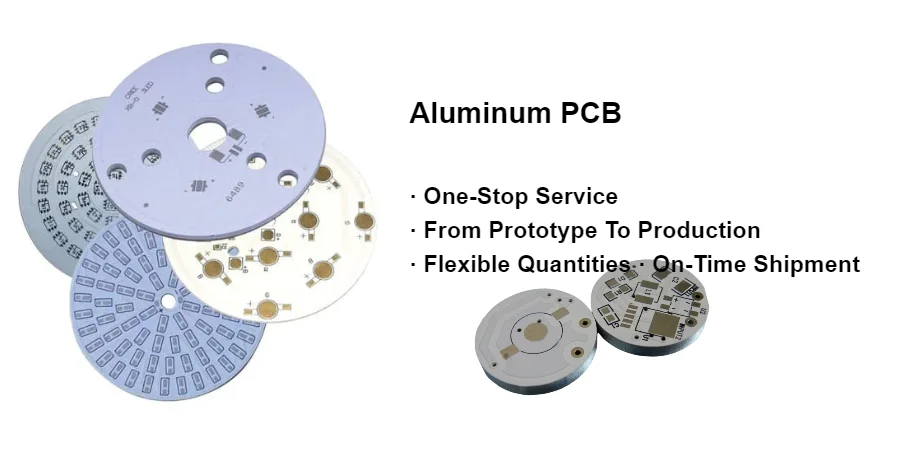
An aluminum PCB, often called an MCPCB or metal-core PCB, is usually chosen when the board itself has to become part of the heat path. That is common in LED modules, power conversion stages, and other layouts where standard FR-4 no longer gives enough thermal margin.
The real selection question is whether your design needs a metal-core thermal platform, a high-thermal PCB, a ceramic PCB, or a heavier-copper FR-4 structure. Those platforms solve different thermal problems and should not be treated as interchangeable.
The focus here is engineering-commercial decisions: when a metal core PCB is the right fit, what in the stack-up actually matters, and what to confirm with your fabricator before you release LED or power hardware. For detailed fabrication parameters, thermal conductivity options, and dielectric breakdown thresholds, refer to our metal core and aluminum PCB capabilities. Broader material-selection work belongs in the materials center or the related PCB material selection guide.
Quick Answer Use an aluminum PCB when the board itself must become part of the heat path and the circuit still fits a metal-core route. The main failure chain is usually not "FR-4 was a little warm." It is
heat source + dielectric + board-to-sink interfaceleft underdefined -> hotspot stays trapped at the LED or power device -> solder fatigue, discoloration, delamination, or output drift appears in pilot build or field use -> the team is forced back into platform or assembly rework.
Table of Contents
- 1. What an Aluminum PCB Actually Solves
- 2. How the MCPCB Stack-Up Changes Thermal Behavior
- 3. When Aluminum PCB Is the Right Choice
- 4. Design and Release Checks Before You Send the Files
- 5. What to Ask an Aluminum PCB Manufacturer or Assembly Partner
- Conclusion: Use MCPCB as a Platform Choice, Not a Default
1. What an Aluminum PCB Actually Solves
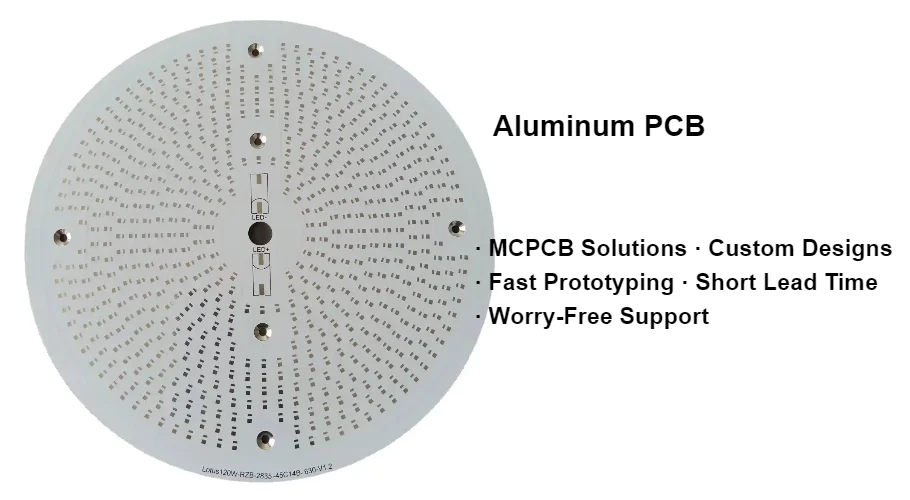
An aluminum PCB is a printed circuit board built on a metal base, typically aluminum, with a dielectric layer between the base and the copper circuitry. The metal base spreads heat, while the dielectric has to balance insulation with thermal transfer.
That matters when your main constraint is not just routing density, but moving heat away from LEDs, MOSFETs, rectifiers, or power resistors into a chassis, heatsink, or enclosure wall.
Common triggers for moving from standard FR-4 to MCPCB include:
- LED arrays with concentrated thermal load
- compact power supplies where local hot spots dominate reliability risk
- boards that must bolt directly to a housing or heat spreader
- products where board rigidity and thermal spreading matter more than multilayer routing freedom
Aluminum PCB is not the answer to every thermal problem. If the design needs dense multilayer interconnect, very high isolation, or a more extreme thermal substrate, the better path may be a high-thermal PCB, ceramic PCB, or a different material strategy from the broader materials center.
Why teams choose MCPCB
- Better heat spreading than ordinary FR-4 in board-level thermal paths
- Good mechanical stiffness for larger lighting and power boards
- A simpler hardware stack when the board mounts directly to metalwork
- Practical fit for single-sided or limited-layer LED and power layouts
Where teams overuse it
- High-pin-count designs that really need conventional multilayer routing
- Projects that need performance proof but have not done thermal modeling or validation
- Builds where the real bottleneck is interface material, enclosure contact, or airflow rather than the bare board
2. How the MCPCB Stack-Up Changes Thermal Behavior
The stack-up matters more than the phrase "aluminum PCB." In practice, the dielectric layer usually dominates thermal impedance, so two MCPCBs with the same aluminum base can behave very differently depending on dielectric thickness, material family, copper weight, and board layout.
Typical layers are:
Copper circuit layer Carries current and helps spread heat laterally.
Thermally conductive dielectric Electrically isolates the copper from the base while allowing heat transfer. This layer is usually the key tradeoff between thermal performance and isolation.
This is also where low-cost MCPCB buying turns dangerous. Some procurement teams push for the cheapest aluminum board available, and low-end suppliers respond by forcing the dielectric extremely thin, sometimes below 75 um, to advertise better thermal conductivity from otherwise weak resin systems. On paper, the board still looks like a thermal upgrade. In reality, that thin dielectric may be full of microvoids and process variation that only show up under electrical stress.
The board may light normally at low voltage and room temperature. The failure appears later, during Hi-Pot at final test or during a field surge event. A poor dielectric can break down instantly, arc from the copper circuit into the aluminum base, and dump hazardous voltage into the metal chassis. The result is not a mild thermal defect. It is catastrophic shorting, destroyed PCBA, and a real touch-safety problem. That is why the true buying decision in an aluminum PCB is often the dielectric, not the aluminum. The red line is the physical balance between thermal conductivity and breakdown voltage.
Aluminum base Adds rigidity and spreads heat into the mechanical structure.
Surface finish and solder mask Affect solderability, corrosion resistance, optical reflectivity, and inspection behavior. If surface-finish tradeoffs matter, route the discussion to PCB surface finishes instead of treating finish choice as a thermal afterthought.
This is also why datasheet values must be handled carefully. Exact IMS material properties may be available for specific supplier products, but those are material-level parameters, not guarantees for final board temperature, junction temperature, or field life.
3. When Aluminum PCB Is the Right Choice
Aluminum PCB is usually a strong fit when the board's job is to conduct heat into a mechanical structure with relatively simple circuitry.
Typical use cases include:
- LED lighting modules, light engines, and driver-adjacent boards
- power conversion stages with limited board complexity
- automotive or industrial lighting subassemblies
- power modules that mount to metal chassis parts
- products that benefit from a rigid, thermally active baseplate-style PCB
It is usually a weaker fit when you need:
- dense multilayer routing
- hybrid high-speed digital structures
- ceramic-level thermal or dielectric behavior
- a direct substitute for enclosure, heatsink, or interface-material engineering
For broader material comparison work, start with the PCB material selection guide and then branch into the related page that matches the real constraint: metal core PCB, high-thermal PCB, or ceramic PCB.
4. Design and Release Checks Before You Send the Files
A useful MCPCB release review should confirm more than copper and outline. At minimum, check:
Thermal path definition Identify the main heat sources, the intended exit path, and whether the board is expected to couple into a chassis, external heatsink, or enclosure.
Dielectric tradeoff Confirm the required balance between insulation and heat transfer instead of selecting dielectric only by marketing conductivity language.
Copper and current spreading Review copper thickness, pour strategy, pad geometry, and localized current density.
Surface finish and board surface intent Decide whether the finish choice is being driven by solderability, corrosion handling, optical reflectivity, or downstream assembly controls. If that choice is still open, move it to the PCB surface finishes decision path instead of leaving it implicit.
Mounting interface Define screws, flatness expectations, contact surfaces, and any thermal interface material needed between the board and the next thermal mass.
Electrical isolation and clearance This is especially important for mains, automotive, and other higher-voltage designs where the metal base changes the insulation discussion.
Assembly profile and solder joint risk MCPCB assembly is a materials-plus-process problem. Thermal mass, solder paste selection, and measured reflow profiling should be reviewed together, especially for LED and power boards.
5. What to Ask an Aluminum PCB Manufacturer or Assembly Partner
If you are sourcing MCPCB, the most useful questions are specific:
- Which base-metal and stack-up options are actually supported for this design?
- How many layers are realistic for the intended metal-core structure?
- Which surface finishes and solder-mask systems are recommended for the application?
- How is dielectric choice reviewed against isolation and thermal-path requirements?
- What DFM feedback will be given on copper balance, routing limits, and mounting details?
- How will assembly profiling and inspection be handled for the board's thermal mass?
- What release notes, stack-up approvals, or mounting-interface details should be frozen before pilot build?
Those questions map the project to a real support path faster than generic supplier comparison. For APT-specific routing, the nearest pages are metal core PCB, high-thermal PCB, PCB surface finishes, and quote.
Conclusion: Use MCPCB as a Platform Choice, Not a Default
Aluminum PCB works well when the board must participate directly in the thermal path and the circuit complexity still fits a metal-core structure. The decision should be based on heat flow, isolation needs, assembly method, and mechanical integration, not on the assumption that every hot board needs aluminum.
For straightforward metal-core builds, go deeper on the metal core PCB page. If the project is really a broader substrate tradeoff, compare it against the materials center, high-thermal PCB, and ceramic PCB paths before locking the stack-up.
Next steps with APTPCB
If you are developing a high-power LED engine, an automotive converter, or a high-voltage power board, the real fear is usually not only heat. It is whether the dielectric will delaminate after reflow, or whether the entire project will fail UL or CE stage Hi-Pot because the MCPCB stack-up was pushed too far toward thermal marketing numbers and away from insulation margin.
Send the full package to [email protected], or route it through the metal core PCB thermal review request. Include the Gerber or ODB++, target thermal conductivity in W/mK, dielectric-thickness requirement, and the Hi-Pot or isolation-voltage specification.
APTPCB's thermal-management and materials engineering team will return an MCPCB Dielectric Safety & Thermal Review within 24 hours. The review will balance thermal impedance against high-voltage clearance and insulation demands, and lock a metal-core route that is defensible before you put a high-risk build into mass production.
Useful related pages:
Public references
Bergquist thermal materials and interfaces overview Supports the board-to-sink interface framing used when MCPCB performance depends on more than the bare substrate.
APTPCB Metal core PCB page Supports the public MCPCB manufacturing context used throughout the article.
APTPCB High thermal PCB page Supports the route-selection framing used when IMS is only one of several thermal platform options.
APTPCB Ceramic PCB page Supports the comparison boundary between ceramic and metal-core thermal platforms.
Author and review information
- Author: APTPCB materials, thermal, and DFM content team
- Technical review: thermal-platform, assembly-profile, and release-package engineering team
- Last updated: 2026-05-15