Megtron high-speed PCB manufacturing

High-Speed Digital Materials

Panasonic Megtron 4 / 6 / 7 / U PCB Manufacturing

APTPCB is a Megtron PCB manufacturer for controlled-impedance 56G and 112G PAM4 SerDes channels. We engineer spread-glass stackups, VLP/HVLP copper, TDR/VNA and COM/eye analysis, with backplanes up to 40+ layers.

Df 0.008 -> 0.001
Megtron 4 -> U
112G PAM4
Target Data Rate
40+ Layers
Backplane Capable

Get an Instant Quote

Megtron 4 / 6 / 7 / USeries Scope
Spread GlassSkew Control
VLP / HVLPCopper Foil
Sequential LamStacked Microvias
TDR + VNASI Validation
COM / EyeAnalysis Available
Inspection RecordsQuality Evidence
IST OptionWhen Ordered
Megtron 4 / 6 / 7 / USeries Scope
Spread GlassSkew Control
VLP / HVLPCopper Foil
Sequential LamStacked Microvias
TDR + VNASI Validation
COM / EyeAnalysis Available
Inspection RecordsQuality Evidence
IST OptionWhen Ordered

Why Engineers Specify Megtron

Megtron PCB Manufacturer for High-Speed Laminates

APTPCB manufactures high-speed digital boards using Panasonic's Megtron family for SerDes backplanes and channel designs. Megtron 4 (Df ~0.005 at 1 GHz) is a low-loss FR-4 alternative for PCIe Gen3/Gen4 and 10-25 Gbps applications. Megtron 6 (Df ~0.002) supports 56G PAM4 backplanes and data-center switch ASICs. Megtron 7 (Df ~0.0015 with improved Z-axis CTE) targets high-layer-count backplanes where microvia reliability and signal integrity must be reviewed together. Megtron U and Megtron 8 address 112G/224G PAM4 design studies.

Our engineering team prepares spread-glass options (1035, 1067, 2116), VLP/HVLP copper choices, layer-by-layer dielectric proposals, copper roughness inputs for Causal RLGC modeling, and Polar Si9000e impedance simulations for high-speed PCB channels. Sequential lamination and buried/blind microvia routes can support 40+ layer backplanes; final construction and acceptance criteria are confirmed during stack-up and RFQ review.

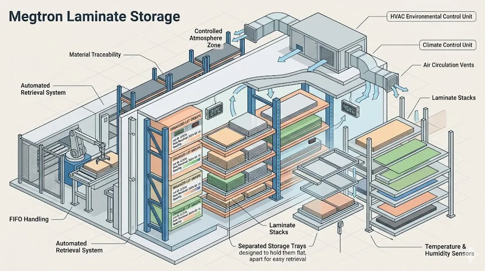
Megtron laminate storage

Material Portfolio

Megtron 4 vs Megtron 6 vs Megtron 7

Compare the Megtron grades commonly considered for high-speed digital boards; final material and glass choices depend on channel, stack-up and RFQ review.

SeriesBase ChemistryDk RangeDf (Typ. @ 10 GHz)Key CharacteristicsPrimary Applications
Megtron 4 (R-5725 / R-5620)Modified PPE resin / E-glass3.80.005Low-loss FR-4 alternative. Tg 176 deg C, Td 360 deg C. Processes with standard FR-4 equipment and chemistry. Lead-free process options can be reviewed in the RFQ. Good balance of electrical performance and cost for mid-speed digital applications.PCIe Gen3/Gen4, 10–25 Gbps SerDes, network routers, server boards, measuring instruments
Megtron 6 (R-5775 / R-5670)PPE resin / E-glass (standard and low-Dk glass)3.4 (N-glass) / 3.7 (E-glass)0.002Ultra-low-loss, industry benchmark for high-speed digital. Tg 185 deg C, Td 410 deg C. Available with standard E-glass or low-Dk N-glass. Excellent HDI and thermal performance. FR-4-compatible processing. Spread-glass weave options for skew control.56G PAM4 backplanes, data center switches, 400G Ethernet, AI/HPC interconnects, high-speed IC testers
Megtron 7 (R-5785 / R-5680)Advanced PPE resin / E-glass (standard and low-Dk glass)3.3 (N-glass) / 3.6 (E-glass)0.0015Next-generation ultra-low-loss with improved Z-axis CTE for high-layer-count reliability. Tg 200 deg C, Td 400 deg C. May support longer channel designs than Megtron 6 when the complete stack-up and loss budget allow. IST microvia testing can be scoped for high-layer-count backplanes.112G PAM4 backplanes, 800G Ethernet switches, HPC/AI server interconnects, next-gen switch ASIC host boards
Megtron 8 (R-5795 / R-5690)Next-gen ultra-low-loss resin / E-glass3.10.0012Panasonic's latest ultra-low-loss grade for the most demanding next-generation channels. Tg 220 deg C, Td 370 deg C. Designed for 224G PAM4 and beyond. FR-4-compatible processing maintained.224G PAM4, next-gen co-packaged optics, 1.6T Ethernet, advanced AI accelerator interconnects
R-1755VHigh-Tg FR-4 epoxy / E-glass4.40.016Standard high-Tg FR-4 baseline from Panasonic. Tg 173 deg C, Td 350 deg C. Cost-effective option for non-critical signal layers in hybrid stack-ups or applications where electrical loss is not the primary concern.Power/ground layers in hybrid stacks, general multilayer PCBs, non-critical digital, cost-sensitive applications

Megtron 4, Megtron 6 (R-5775/R-5670), and Megtron 7 (R-5785/R-5680) cores and prepregs can be specified with common thicknesses, glass styles (1035, 1067, 1078, 2116), and VLP/HVLP copper options subject to RFQ confirmation. Megtron 8 and non-standard constructions require material-availability review.

Engineering Reference

Megtron Electrical and Mechanical Properties

Comprehensive material data for the most frequently requested models. All dielectric values measured at 10 GHz using clamped stripline resonator method per IPC-TM-650 2.5.5.5 unless otherwise noted. Data sourced from manufacturer published datasheets.

PropertyMegtron 4Megtron 6 (E-glass)Megtron 6 (N-glass)Megtron 7 (E-glass)Megtron 7 (N-glass)Megtron 8Test Method
Dk @ 1 GHz3.83.73.43.63.33.1IPC-TM-650 2.5.5.5
Df @ 1 GHz0.0050.0020.0020.00150.00150.0012IPC-TM-650 2.5.5.5
Tg (deg C, DSC)176185185200200220IPC-TM-650 2.4.25
Td (deg C, TGA 5%)360410410400400370IPC-TM-650 2.4.24.6
Flammability (UL 94)V-0V-0V-0V-0V-0V-0UL 94
Lead-Free CompatibleYesYesYesYesYesYes-
Plasma RequiredNoNoNoNoNoNo-
FR-4 Compatible ProcessingYesYesYesYesYesYes-
Spread Glass AvailableYesYesYes (all)YesYes (all)Yes-
Common Glass Styles1080, 2116, 76281035, 1078, 21161035, 1078, 21161035, 1067, 21161035, 1067, 21161035, 1067, 2116-
Panasonic Part # (Laminate)R-5725R-5775R-5775(N)R-5785R-5785(N)R-5795-
Panasonic Part # (Prepreg)R-5620R-5670R-5670(N)R-5680R-5680(N)R-5690-

Data from Panasonic Industrial published datasheets. Dk/Df values are at 1 GHz per Panasonic standard test method. Megtron grades generally use standard FR-4 lamination parameters; the final desmear and through-hole route is confirmed for the selected construction.

Megtron 6 vs. I-Tera MT40

Head-to-Head: Panasonic Megtron 6 vs. Isola I-Tera MT40

For 56G PAM4 high-speed digital designs, engineers frequently evaluate Megtron 6 against Isola I-Tera MT40. Both are ultra-low-loss thermoset materials that process like standard FR-4, but they offer distinct advantages depending on stack-up requirements and the broader Isola laminate family already qualified in the program.

PropertyMegtron 6 (E-glass)Isola I-Tera MT40Comparison & Impact
Dk @ 10 GHz3.603.45I-Tera has a slightly lower Dk, allowing for marginally wider traces when targeting 100 ohm differential pairs.
Df @ 10 GHz~0.004 (@10G) / 0.002 (@1G)0.0031Both laminates provide highly comparable insertion loss performance perfectly suited for 56G channels.
Tg (Glass Transition)185 deg C200 deg CI-Tera provides a slightly higher Tg, offering excellent thermal reliability for high-layer-count boards.
ProcessingStandard FR-4 ChemistryStandard FR-4 ChemistryBoth completely eliminate the need for costly and time-consuming PTFE plasma desmear.
Hybrid RF UsePrimarily Digital UseExcellentI-Tera is specifically designed to be thermally compatible with Astra MT77 for RF/digital hybrid boards.

Megtron 6 and I-Tera MT40 are both candidates for pure digital backplanes; the suitable option depends on the stack-up, loss budget, hybrid RF needs and RFQ review.

Manufacturing Process

Megtron PCB Manufacturing Process

Processing Megtron materials requires equipment, chemistry, and process knowledge beyond standard FR-4 manufacturing. Our team reviews the intended material, glass, copper and lamination route before production so the released build matches the approved stack-up.

Production records can include drill, etch, lamination, plating and inspection data tied to the lot or order. The supplied record set is agreed in the RFQ and supports traceability without implying a universal test package.

Our CAM engineering team reviews incoming designs for manufacturability, impedance simulation inputs (Polar Si9000 with manufacturer Dk/Df curves), stack-up optimization recommendations, and material selection guidance before release.

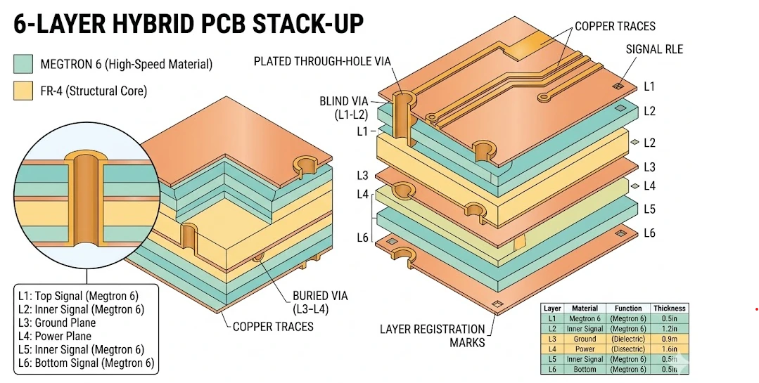
Megtron hybrid PCB cross-section

Reference Stack-Ups

Megtron Stack-Up and Glass Selection

Representative configurations for engineering discussion. Final dielectric thickness, glass style, copper roughness, press profile and acceptance limits are confirmed against the released RFQ.

ConfigurationLayersSignal CoresStructuralBonding SystemApplications
Megtron 6 Full Stack4-20Megtron 6 all signal layers-Megtron 6 prepreg56G PAM4 backplanes, data center switches, 400G Ethernet
Megtron 7 Full Stack4-40Megtron 7 all signal layers-Megtron 7 prepreg112G PAM4, 800G Ethernet, HPC/AI interconnects
Megtron 6 + Megtron 4 Hybrid4-20Megtron 6 (signal)Megtron 4 (pwr/gnd)Megtron 4 prepregCost-optimized high-speed boards, server backplanes
Megtron 6 + FR-4 Hybrid4-16Megtron 6 (signal)Standard FR-4 (pwr/gnd)Standard prepregCost-sensitive networking, general high-speed digital
Megtron 7 + N-glass4-40Megtron 7 (N-glass signal)Megtron 7 (E-glass structural)Megtron 7 prepregUltra-low-loss backplanes, next-gen switch ASIC host boards
Megtron 8 Ultra-Low-Loss4-20Megtron 8 all signal layers-Megtron 8 prepreg224G PAM4, co-packaged optics, 1.6T Ethernet
Megtron + I-Tera MT40 Hybrid4-16Megtron 6 (digital)I-Tera MT40 (RF layers)I-Tera MT40 prepregRF/digital hybrid boards, automotive radar + digital processing
R-1755V Standard4-12R-1755V all layers-R-1755V prepregGeneral multilayer, power/ground in hybrid stacks, cost-sensitive digital

Fabrication Capabilities

Megtron-Specific Manufacturing Controls

Six core capabilities that differentiate our Megtron production from general-purpose PCB manufacturing for high-speed PCB programs.

01

Standard FR-4 Chemistry Processing

Megtron laminates are PPE thermoset resin-based and process with standard FR-4 chemistry without plasma desmear, special surface activation, or modified drill programs. All Megtron grades use the same lamination pressures, temperatures, and cure times as conventional FR-4.

02

Optimized Drill Programs for High-Layer-Count Builds

Megtron laminates process with standard FR-4 drill parameters - no reduced speeds or special PTFE handling required. For high-layer-count backplanes, we optimize drill programs with controlled chip-load feed rates, appropriate entry/backup materials, and aspect-ratio-specific parameters.

03

Controlled Impedance & Precision Etching

Our wet-etch process is set up against the released trace geometry and impedance targets. Where TDR coupons are ordered, measured values are documented against the approved simulation targets for the build.

04

Hybrid Stack-Up Engineering & Lamination

Different Megtron grades can be combined within a single stack-up - for example, Megtron 6 signal layers with Megtron 4 or standard FR-4 structural layers. Our CAM engineers model impedance at every dielectric boundary, select prepreg grades for each interface, and validate the lamination cycle with thermocouple-monitored test runs.

05

Humidity-Controlled Storage & Material Bake Protocols

Megtron laminates are stored in climate-controlled conditions and undergo documented pre-lamination bake cycles when required. Typical bake parameters are 2-4 hours at 105-120 deg C in calibrated forced-air convection ovens, with exact temperature and duration determined by the specific material model, core thickness, and copper cladding weight.

06

RF Surface Finish Selection & PIM Control

Surface finish selection directly impacts high-frequency insertion loss, passive intermodulation, and solder joint reliability on Megtron substrates. Typical recommendations are immersion silver for the lowest surface resistivity on RF signal traces, ENIG for assemblies requiring multi-reflow compatibility, and ENEPIG for antenna boards subject to PIM qualification.

Quality & Validation

Megtron SI Validation

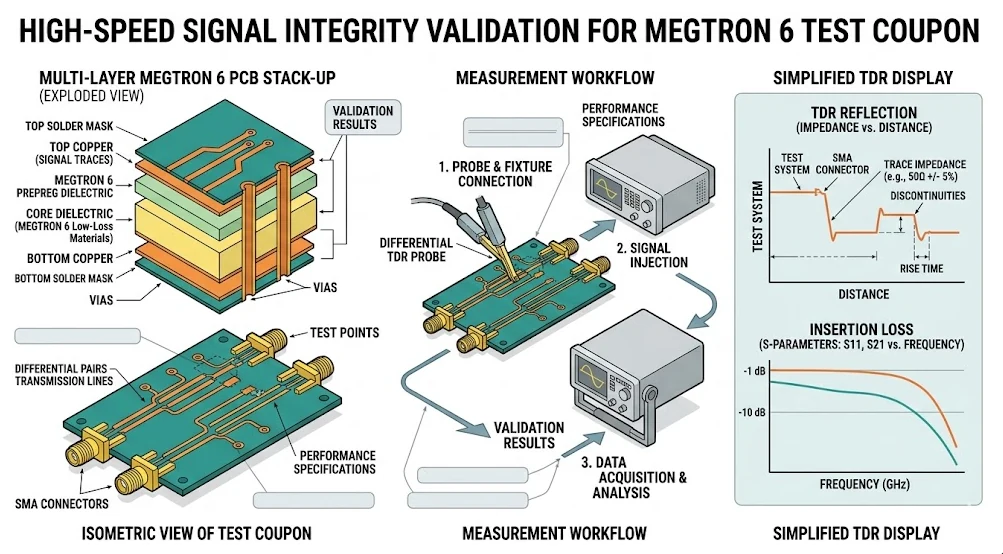
Megtron SI validation is scoped to the released RFQ and can compare impedance targets with TDR coupon data, insertion-loss sweeps, COM or eye-diagram analysis, and the agreed channel model. Typical electrical values are design inputs, not a finished-channel guarantee.

Where ordered, SI validation outputs can include VNA S-parameter sweeps on dedicated test vehicles, cross-section micrographs with dimensional annotations, and IST reliability testing per IPC-TM-650 2.6.26. Material documentation and inspection records are supplied according to the agreed order package.

Inspection scope, acceptance criteria, traceability depth and environmental or reliability testing are confirmed for the application during RFQ review.

Megtron TDR validation workstation

Industry Applications

Where Megtron PCBs Serve

Megtron substrates serve the most demanding applications across telecommunications, automotive, aerospace, defense, data center, medical, and industrial markets.

Telecommunications

5G & Wireless Infrastructure

5G base station infrastructure including massive MIMO antenna control boards, beamforming digital processing modules, and baseband units. Megtron's low-loss characteristics support the high-speed SerDes channels connecting FPGA/ASIC to RF front-end modules.

Satellite & Space

SATCOM & LEO Terminals

High-speed digital processing boards for satellite ground terminals and LEO gateway modems. Megtron 6 and Megtron 7 serve the 56G and 112G PAM4 SerDes channels in satellite communication baseband processing units and ground station digital equipment.

Defense

Military Radar & Electronic Warfare

Military and defense digital processing boards for radar signal processing, electronic warfare computing, and secure communications. Megtron 6 and 7 support high-speed digital backplanes and signal processing boards in defense systems.

Automotive

24 GHz & 77 GHz ADAS Radar

Automotive ADAS digital processing boards, in-vehicle networking, infotainment system host boards, and EV battery management digital controllers. Megtron 6 and Megtron 7 support the high-speed interfaces in autonomous driving compute platforms.

Test & Measurement

Calibration & Reference Standards

High-speed IC test equipment including ATE load boards, IC tester interface boards, and burn-in boards for semiconductor validation. Megtron 6 is widely specified for IC tester channel boards where signal integrity at 56G+ directly affects test accuracy and throughput.

Industrial & IoT

Wireless Connectivity & ISM-Band

Data center and cloud computing infrastructure including top-of-rack switches, spine switches, storage controllers, and AI/HPC accelerator host boards. Megtron 6 dominates 400G Ethernet switch boards, while Megtron 7 and 8 target 800G/1.6T next-generation platforms.

Material Selection Guide

Megtron PCB RFQ Requirements

Use the following engineering inputs to start a Megtron PCB manufacturer review. Recommendations remain provisional until the stack-up and RFQ are approved.

10-25 Gbps, Cost-Conscious - Megtron 4

For PCIe Gen3/Gen4 and 10-25 Gbps SerDes applications, Megtron 4 provides a meaningful reduction in insertion loss versus standard FR-4 at a moderate cost premium. It processes identically to conventional FR-4, making it the logical first step up from standard FR-4 when signal-integrity margins are tight.

25-56 Gbps, High-Performance - Megtron 6

Megtron 6 is the industry benchmark for 56G PAM4 backplanes and data center switch ASICs. Available with standard E-glass or low-Dk N-glass cloth, it provides materially lower loss than standard FR-4 on long differential traces. Spread-glass weave options control differential skew.

56-112+ Gbps, Longer-Reach Studies - Megtron 7 / Megtron U

For 112G PAM4 and beyond, Megtron 7 and Megtron U can be evaluated for longer-reach or high-layer-count designs. Channel length, loss budget, glass choice and Z-axis reliability targets remain design-dependent and require SI review.

Standard FR-4 Layers in Hybrid Stacks - R-1755V

For non-critical layers in hybrid Megtron stacks such as power, ground, and low-speed control, Panasonic R-1755V provides a standard high-Tg FR-4 baseline at lower cost. Megtron 4 also serves as a cost-effective structural layer material where premium Megtron 6/7 is reserved for the highest-speed signal layers.

RFQ Checklist

Include the target data rate, maximum channel length, layer count, glass style, copper roughness, impedance targets, and quantity. Also identify the loss budget, surface finish, test coupon needs, SI validation outputs where ordered, material documentation, and inspection records. APTPCB uses these inputs to prepare a stack-up proposal; final material selection and acceptance criteria follow stack-up and RFQ review.

FAQ

Megtron PCB Manufacturing FAQ

How does Megtron 6 compare to Isola I-Tera MT40?
Both are ultra-low-loss thermoset laminates that process with standard FR-4 chemistry. Megtron 6 offers more flexibility for high-layer-count digital designs with its low-Dk N-glass option, while I-Tera MT40 provides multiple Dk options for impedance flexibility and is thermally compatible with Isola Astra MT77 for hybrid RF/digital builds used in backplane and switch-card programs.
Can Megtron grades be mixed in a single stack-up?
Yes. Hybrid stack-ups using different Megtron grades such as Megtron 6 signal layers with Megtron 4 or R-1755V structural cores are common for cost optimization. Because all Megtron series utilize compatible thermoset resins and process with identical lamination parameters, they bond together without the delamination risks associated with mixing PTFE and FR-4. Our engineers typically formalize this through a documented stack-up definition process before release.
How is Megtron material availability confirmed for an RFQ?
APTPCB confirms the requested Megtron grade, core or prepreg part number, thickness, glass style and copper foil against the order scope. Megtron 4, 6, 7, U, 8 and non-standard constructions remain subject to current material-availability review before the stack-up and quotation are released.
Can Megtron substrates be hybridized with standard FR-4?
Yes. Megtron grades are fully compatible with standard FR-4 for hybrid construction. Common configurations include Megtron 6 or Megtron 7 signal layers with standard 370HR or Megtron 4 power and ground layers, reducing material cost while maintaining signal integrity on critical channels.
What surface finishes do you recommend for Megtron-based high-speed boards?
Immersion silver is our default for high-frequency RF signal traces because it provides very low surface resistivity. ENIG is recommended when the assembly includes fine-pitch BGA, QFN, LGA, or flip-chip components requiring multi-reflow capability. ENEPIG is specified for antenna boards that must pass PIM qualification. HASL is generally not recommended for high-speed boards because the resulting uncontrolled surface roughness increases conductor loss.
What determines the schedule for a Megtron PCB order?
Schedule depends on the released data, layer count, material and glass availability, fabrication route, test scope and quantity. APTPCB confirms the applicable schedule during RFQ review rather than promising a fixed turnaround before those inputs are checked.
Do you offer turnkey PCBA assembly services for Megtron-based boards?
Yes. We provide full turnkey PCB assembly for Megtron-based boards including component sourcing, solder paste printing, SMT placement, reflow soldering with thermal profiles optimized for Megtron substrate characteristics, through-hole insertion, AOI, X-ray inspection, ICT or flying probe testing, and functional testing.
What manufacturing records can accompany a Megtron PCB order?
The agreed order package can include material documentation, stack-up and impedance records, TDR data where ordered, SI validation outputs where ordered, and inspection records. Cross-sections, IST or environmental reports can be added when the application and RFQ call for them; the final record set is confirmed before release.

Interactive Tool

Megtron Grade & Data Rate Selector

Use the recommendation as an engineering starting point only. Final Megtron grade, glass style, copper and test scope are confirmed through stack-up and RFQ review.

Select Target Data Rate
Select a data rate to see a starting-point grade, copper foil and glass style; final choices follow stack-up and RFQ review.

Global Engineering Reach

Megtron PCB Manufacturing for Engineers Worldwide

Data-center, network-switching and high-speed storage teams use Megtron 6 and Megtron 7 for 56G and 112G PAM4 channel designs. APTPCB reviews stack-up and DFM inputs as part of the RFQ.

North America
USA · Canada · Mexico

Defense contractors, telecom OEMs, and hardware startups across the US and Canada use APTPCB for prototype and NPI builds. Documentation scope is agreed during the RFQ.

Data CentersNetworking112G SerDes
Europe
Germany · UK · Sweden · France

Automotive radar suppliers in Germany, defense electronics teams in the UK and France, and Scandinavian wireless R&D labs source prototypes and production-intent boards through our platform.

TelecomStorageHigh-Speed
Asia-Pacific
Japan · South Korea · Taiwan · India

5G base station manufacturers, satellite terminal developers, and hardware startups across APAC use our online quoting platform for prototypes and NPI runs with DFM scope agreed during the RFQ.

Server OEM5G SwitchNPI
Israel & Middle East
Israel · UAE · Saudi Arabia

Aerospace radar, defense EW, and SATCOM programs in the region rely on our extended qualification documentation packages and material traceability for defense procurement compliance.

Defense C2Radar DSPHigh-Speed

Megtron PCB Manufacturer RFQ

Send Gerber files or an early design brief with target data rate, channel length, layer count, glass style, copper roughness, impedance targets and quantity. APTPCB can prepare a stack-up proposal, impedance/TDR data, SI validation outputs where ordered, material documentation and inspection records for the agreed order scope.