
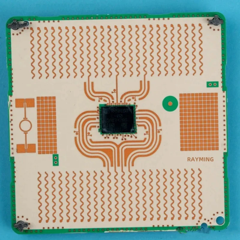
Industrial
Industrial controller
Multiple PCBAs, displays, cooling and harnesses may be integrated; load, safety or endurance tests must be defined in the customer test plan.
MechanicsWiringFinal test
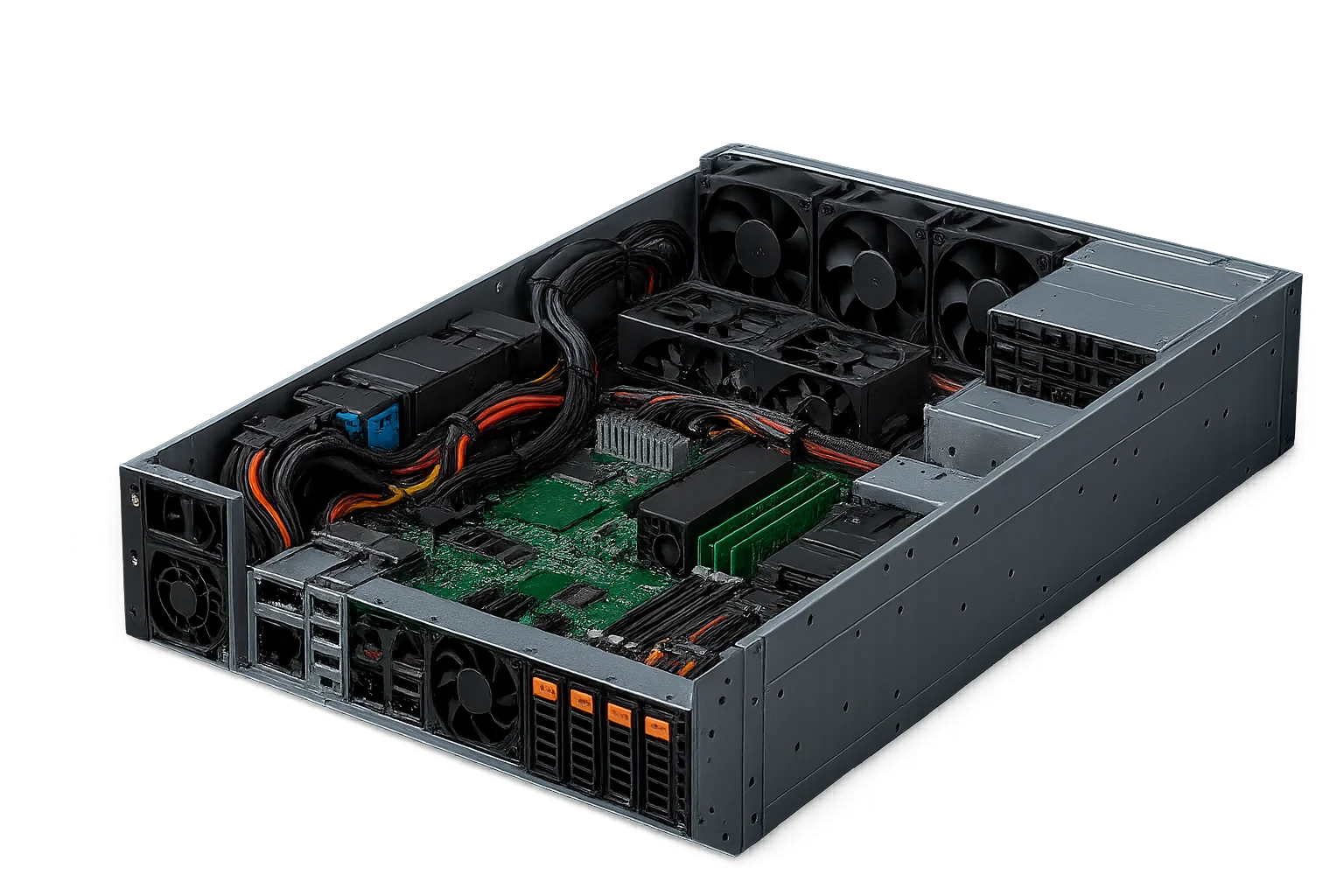
SYSTEM INTEGRATION
Box build assembly is the electromechanical system-integration stage after board assembly: verified PCBAs are installed with enclosures, harnesses and other components, then programmed, tested and packed when those steps are included in the approved customer scope.
The page is focused on system-level integration after board assembly, not only SMT/THT placement or cable fabrication.
Dimensions, weight, interfaces, tooling and test equipment are reviewed before quotation.
Mechanical, wiring, firmware/test and pack-out each receive defined acceptance criteria.
BOM, drawings, firmware and test plans are tied to the agreed evidence scope.
Box build assembly is the higher-level assembly step that joins verified PCBAs with mechanical hardware, wire harnesses, displays, power modules, firmware and final test so the result can ship as a usable product or sub-system.
Unlike SMT/THT, component-sourcing or harness pages, this page addresses the interfaces and approvals of the complete system: mechanical fit, wiring, firmware, final test, labeling and shipping condition.
APTPCB confirms the executable scope only after reviewing the product package. Final regulatory approval, system performance, field safety and end-product compliance remain the customer's responsibility.
RELEASE EVIDENCE
The practical risk in box build is not simply whether parts are installed; it is whether every installed part can be traced to a drawing, route, torque value, firmware revision and test limit. A release gate turns those requirements into evidence before shipment.
When contractually specified, acceptance references may include IPC-A-610 for electronic assemblies, IPC/WHMA-A-620 for cables and wire harnesses, and ANSI/ESD S20.20 for an ESD control program. Mechanical fit and final test follow approved customer drawings and limits.
RFQ INPUTS
A box-build quote is only accurate when the mechanical, electrical, firmware, test and logistics inputs are all visible at the same time. Missing torque, firmware or packaging data usually creates rework after the first article build.
For NPI, send the best available package and mark unknowns clearly; for repeat production, freeze the revision package before moving into serialized build records.
BOX-BUILD COVERAGE
The build scope is derived from product data, assembly sequence, test plan and required shipping condition before production release.
Mechanical integration
Install PCBAs, displays, fans and hardware to approved drawings; define fit, gap and torque criteria in the RFQ.
Harness integration
Install, label and route customer-supplied or approved harnesses; confirm fabrication and electrical test scope separately.
Firmware & test
Program and run final test to customer files and plans; approve the interface, fixture, limits and log format first.
Packaging & logistics
Prepare accessories, labels, ESD protection and shipping packaging to the approved pack-out drawing.
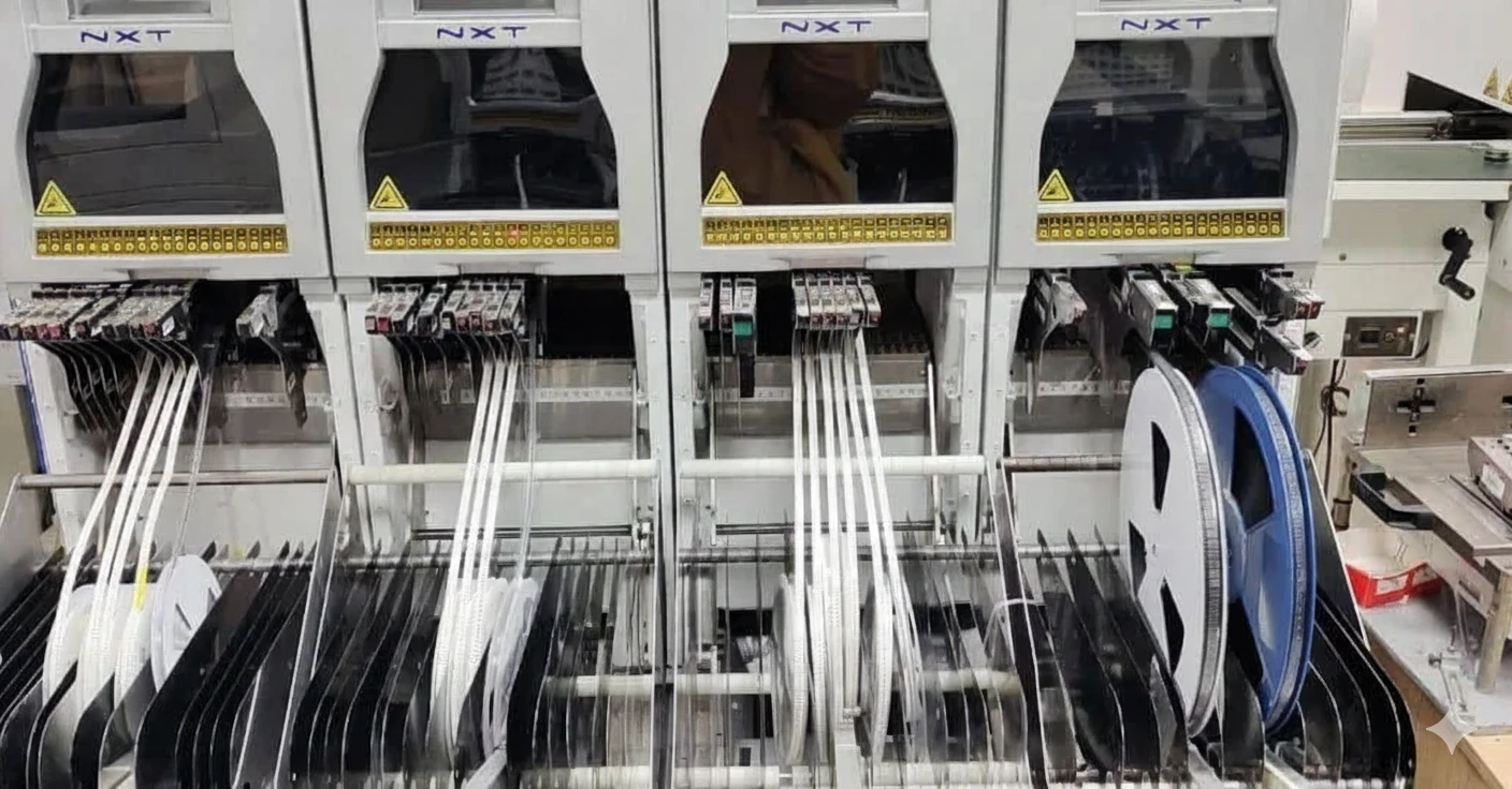
WORKFLOW
From feasibility review to documented product and pack-out release.
Confirm feasibility
Review BOM, drawings, wiring, torque, firmware, test plan and pack-out for completeness and feasibility.
Integrate mechanics
Install PCBA, cooling, displays and hardware to the work instruction; release fit and fastening before closure.
Install wiring
Connect, label and strain-relieve harnesses to the wiring plan; perform the agreed electrical checks.
Firmware & test
Load approved firmware and run the agreed final test with defined limits and evidence.
Pack-out
Verify accessories, manuals, labels and protective packaging against the approved pack-out requirements.
APPLICATIONS
The final configuration depends on approved drawings, test ownership and the required shipping condition.
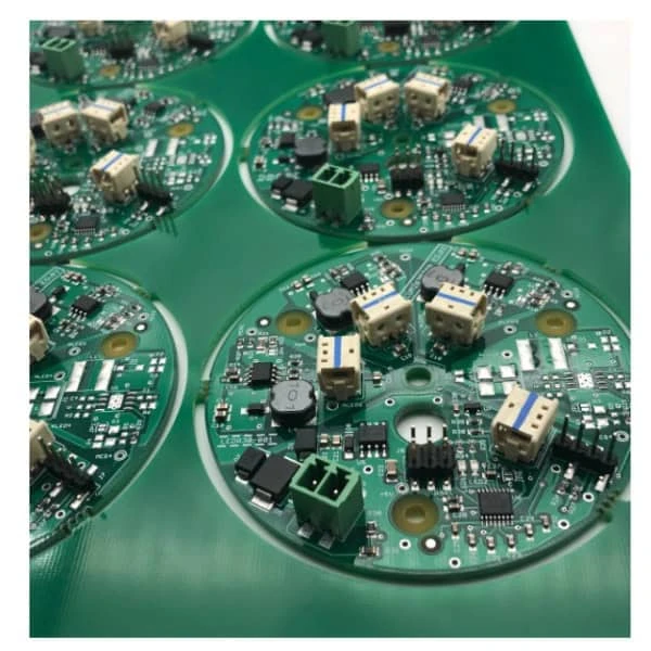
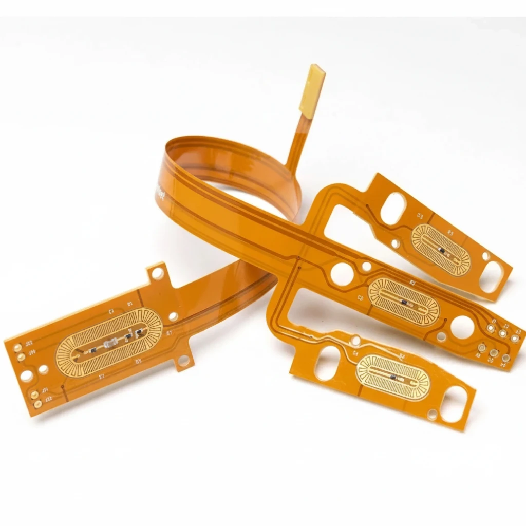
INTEGRATION SCOPE
The capability list is written around release risk: fit, wiring, power-up, firmware, safety and shipment condition.
ESD, MSD, cleanliness, tooling and packaging requirements are reviewed for the product and defined in the manufacturing plan.
QUALITY
Most box-build defects are easier to prevent before final closure, so controls are placed at mechanical, wiring and power-up gates.
Fasteners, tool status, torque requirements, gap and cosmetic criteria are checked against the approved drawing.
Connector orientation, polarity, labeling, strain relief and routing are checked before covers restrict access.
Firmware revision, test fixture, limits, result and required serial-number linkage follow the agreed customer test plan.
Enclosures, cooling and power connections with customer-defined safety and functional tests.
Multiple assemblies, sensors and actuators with defined cleanliness, labeling and test requirements.
Gateway and hub integration with project-specific programming, RF test and packaging.
Accessories, manuals, customer labels and shipping packaging to an approved pack-out drawing.
RELEASE GATES
The differentiator is a defined evidence package that keeps fastening, wiring, firmware, test, pack-out and serial data connected.
Gate 1
Release record
• Fastener type and torque table match the drawing.
• Gap, gasket, panel and label orientation are inspected.
• Nonconforming cosmetic or fit findings are held before electrical release.
Gate 2
Release record
• Connector keying, polarity and label text are verified.
• Strain relief and bend radius are checked against the route drawing.
• Hi-pot is added when the customer test plan requires it.
Gate 3
Release record
• Firmware revision or checksum is captured in the traveler.
• Fixture ID, calibration state and pass/fail limits are recorded.
• The agreed test result is linked to the build record at the defined level.
Gate 4
Release record
• Accessory kit and manual list are verified.
• ESD, foam, carton and pallet requirements are checked.
• Barcode or customer label data is checked to the agreed verification rule.
Cost control
Reviewable cost drivers
• Materials, tools and test fixtures are reviewed together during production planning.
• Changes can be checked against mechanical, electrical and packaging inputs.
Scale control
Reviewable cost drivers
• Variant rules are documented instead of rediscovered by each build.
• Packaging and labeling are approved before production ramp.
Questions engineers and buyers usually ask before releasing a PCBA into full system integration.
Upload the files that define fit, wiring, firmware, test and shipment so the quote can cover the whole release path, not only board assembly.