Medical PCB and PCBA manufacturing for monitoring, imaging, IVD and wearable devices

Medical PCB & PCBA

Medical PCB & PCBA Manufacturing for Regulated Device Programs

Medical PCB manufacturing turns a device's electrical, mechanical, cleanliness and traceability requirements into controlled bare-board and assembly outputs. APTPCB supports monitoring, imaging, IVD, therapeutic and wearable programs with HDI and rigid-flex options, inspection, and project-defined release evidence from prototype through production.

Get an Instant Quote

Rigid / Flex / Rigid-FlexBoard Formats
Laser MicroviasHDI
±5% When SpecifiedImpedance
SPI / AOI / X-RayAssembly Inspection
Flying Probe / FixtureElectrical Test
IPC Class 2 / 3Acceptance
Lot / Board LevelTraceability
Project-DefinedRelease Evidence
Rigid / Flex / Rigid-FlexBoard Formats
Laser MicroviasHDI
±5% When SpecifiedImpedance
SPI / AOI / X-RayAssembly Inspection
Flying Probe / FixtureElectrical Test
IPC Class 2 / 3Acceptance
Lot / Board LevelTraceability
Project-DefinedRelease Evidence

What Is Medical PCB and PCBA Manufacturing?

Medical PCB and PCBA manufacturing is the controlled fabrication, assembly, inspection and release of electronics used inside medical and healthcare equipment. There is no universal “medical-grade PCB” specification: the applicable stackup, acceptance class, cleanliness limit, traceability and test evidence must come from the device risk analysis and purchasing specification.
For buyers, the key question is not whether a supplier serves the medical market. It is whether the supplier can translate your device requirements into a buildable package, identify manufacturing and test gaps before release, hold the agreed revision, and return evidence that supports supplier control and the device history record.

How Should Buyers Evaluate a Medical PCB/PCBA Supplier?

Evaluate the supplier against the risks in your specific device, not a generic capability brochure. The RFQ should connect each critical requirement to a manufacturing control and an objective release record.
  • Design transfer: Can the supplier review stackup, controlled-impedance nets, creepage and clearance, component access, panelization and test access before build?
  • Process control: Are material, revision, approved-vendor, soldering, cleaning and special-process requirements unambiguous?
  • Verification: Are inspection method, test coverage, sampling, limits and disposition rules defined before production?
  • Evidence: Does the agreed shipment package identify the build revision, lot or serial traceability, acceptance results and deviations?

Patient Monitoring and Life-Support Boards: Protect Low-Level Signals

ECG, SpO₂, pressure, temperature and other sensor channels place low-level analog signals beside processors, displays, communications and power conversion. Manufacturing cannot correct an unstable circuit architecture, but it must preserve the approved stackup, copper geometry, grounding intent and component population that the validated design depends on.
For monitoring and life-support assemblies, define controlled-impedance nets where applicable, isolation features, critical component substitutions, test-point access, alarm or watchdog test steps and the functional-test limits supplied by the device team. X-ray, ICT or functional test should be specified according to package geometry and accessible fault coverage, not added as an undefined “100% test” claim.

Medical Imaging PCBs: Control Density, Signal Integrity and Heat

Ultrasound, X-ray, CT, MRI subsystems and endoscopic imaging combine sensitive analog front-ends, high-speed conversion, FPGA or processor interfaces, memory and power rails. Typical PCB risks include crosstalk, impedance discontinuity, registration loss in high-layer-count builds, BGA escape constraints and local thermal concentration.
APTPCB can review HDI, blind or buried microvia, via-in-pad, controlled-impedance and rigid-flex requirements against the supplied stackup and artwork. Quote packages should identify impedance nets and tolerances, copper weights, sequential-lamination requirements, BGA inspection needs, thermal interfaces and any coupon, TDR or microsection evidence required for release.

IVD and Laboratory PCBAs: Define Contamination and Motion-Control Risks

IVD and laboratory instruments often combine optical or electrochemical measurement, pumps, valves, heaters, motors and fluid-adjacent mechanics. Flux residue, leakage paths, connector contamination, motor noise and uncontrolled substitutions can affect repeatability even when the bare circuit passes a basic electrical test.
State the permitted cleaning process, ionic cleanliness limit when required, coating or keep-out areas, sensor and connector handling, motor or heater loads, calibration interface and functional-test method. The PCBA supplier can build and test to those limits; assay performance, calibration validity and instrument-level repeatability remain part of the customer's verification.

Therapeutic and Surgical Electronics: Lock Safety-Critical Inputs

Ventilators, infusion systems, surgical tools and energy-delivery equipment may contain control loops, interlocks, isolation barriers, motor drives and higher-power stages. Safety depends on the complete device architecture, but PCB/PCBA release must still protect the approved component set, polarity, spacing, workmanship and test sequence.
Identify safety-critical components in the BOM and AVL, prohibit unauthorized substitutions, define torque or manual-assembly controls where applicable, and provide test procedures with stimuli, limits and expected responses. Deviations should be documented and dispositioned before shipment rather than absorbed into normal production variation.

Wearable and Home Medical PCBs: Balance Miniaturization and Durability

Body-worn and home-use devices drive smaller rigid-flex, flex and HDI constructions, fine-pitch components, battery management and wireless integration. The manufacturing trade-off is between compact routing and adequate annular ring, bend reliability, assembly access, shielding and rework margin.
Define the flex stackup, bend location and radius, stiffeners, adhesive system, controlled-impedance needs, surface finish, battery and charging test points, coating zones and mechanical outline. Biocompatibility, skin contact, ingress protection and user safety are verified on the finished device and its materials of contact—not inferred from the PCB alone.

Medical Power and Isolation PCBs: Manufacture to the Approved Insulation Design

IEC 60601-1 concepts such as Means of Patient Protection influence the customer's insulation architecture. Required creepage, clearance, slots, material group, working voltage, pollution degree and insulation level must be provided by the device design team; they cannot be selected from a generic PCB capability table.
APTPCB can manufacture the approved geometry, verify specified dimensions and electrical continuity, and control the released material and copper build. Compliance with leakage-current, dielectric-strength, temperature-rise and EMC limits is demonstrated at the power assembly and finished-system level under the customer's verification plan.

Define the Medical PCBA Release Gate Before the Build

A release gate is useful only when it states what is checked, how it is checked, the acceptance limit, the coverage or sample size, and the record returned. “AOI plus functional test” is not a complete quality plan without those details.
Available controls can include solder-paste inspection, automated optical inspection, X-ray for hidden joints, bare-board electrical test, flying probe or ICT where access exists, and customer-defined functional test. First-article, cleanliness, coating, microsection, impedance and traceability records should be included only when required and agreed in the quotation.
Before production, align the control plan with device risk: critical characteristics, approved substitutions, revision control, nonconformance disposition, change notification and the exact shipment dossier.

Medical Device Risk to PCB/PCBA Release Matrix

Use this matrix to convert device-level concerns into supplier controls, objective evidence and complete RFQ inputs.

Buyer riskPCB / PCBA controlRelease evidenceRFQ input
Low-level signal integrityApproved stackup, copper geometry and controlled-impedance processElectrical test plus TDR or coupon data when specifiedImpedance nets, target/tolerance, stackup and coupon requirement
Hidden solder-joint defectsPaste-process control, SPI/AOI and X-ray where package geometry requires itInspection result or report at the agreed coveragePackage list, acceptance criteria, coverage and report format
Residue or leakage pathsDefined cleaning process, handling controls and optional ionic cleanliness testCleanliness result when contractedFlux/cleaning restrictions, limit, method, coating and keep-out areas
Isolation geometryDFM review and manufacture of released creepage, clearance, slots and materialDimensional and electrical inspection to drawingWorking voltage, insulation requirement, dimensions and acceptance limits
Revision or component driftReleased files, BOM/AVL control and agreed substitution/change processBuild revision, lot/serial traceability and approved deviation recordAVL, alternates, change-notification rule, labels and serialization
Environmental or lifetime failureBuild to the customer's qualification specimen and test specificationExternal or supplier test report only when included in scopeProfile, cycles, sample size, fixtures, limits and failure disposition

Final device safety, clinical performance and regulatory conformity remain the responsibility of the legal manufacturer.

Medical PCB Fabrication and Assembly Capability Envelope

Representative capabilities used for initial sourcing. Exact feasibility, tolerances and evidence are confirmed against the released data during DFM and quotation.

ParameterRepresentative capabilityRFQ note
Board formatsRigid, flex, rigid-flex and HDIProvide stackup, flex zones, stiffeners and bend requirements
Layer countUp to 32 layers standard; advanced builds up to 64 after reviewSequential lamination and material availability affect feasibility
Fine lines3/3 mil (0.076 mm); 2/2 mil subject to DFMCopper weight, finished geometry and yield assumptions apply
Laser microvias0.075–0.10 mm; blind, buried, stacked and via-in-pad optionsConfirm aspect ratio, fill, stack and reliability requirements
Controlled impedance±5% when specified and feasibleProvide target, tolerance, stackup, material and coupon requirement
MaterialsFR-4, high-Tg and halogen-free FR-4, polyimide, Rogers/PTFE and ceramicMaterial selection and biocompatibility remain device-level decisions
Surface finishesENIG, immersion silver/tin, OSP, electrolytic gold and lead-free HASLSelect by assembly, contact, shelf-life and reliability requirements
AssemblySMT to 01005, BGA/CSP pitch to 0.3 mm, mixed SMT/THTConfirm package list, placement tolerances and X-ray coverage
Inspection and testSPI, AOI, X-ray, electrical test, flying probe/ICT and customer-defined FCTMethod, coverage, limits and records are project-defined
Acceptance criteriaIPC Class 2 or Class 3 when specifiedIdentify applicable fabrication and assembly documents in the RFQ
Quality and complianceISO 9001:2015, UL; RoHS and REACH supportRequest current certificates and confirm scope during qualification
TraceabilityLot-level and board-level optionsDefine serialization, record retention, labels and shipment dossier

This is not a blanket approval for a medical device. The quotation and approved manufacturing data define the actual scope.

Standards, Evidence and Scope of Responsibility

Reference standards that may shape the customer's PCB/PCBA specification include IEC 60601-1 and IEC 60601-1-2 for medical electrical equipment, ISO 14971 for device risk management, ISO 13485 for medical-device quality systems, ISO 10993-1 for biological evaluation, and IPC-6012, IPC-A-600, IPC-A-610 and J-STD-001 for board and assembly requirements.
Citing a standard does not mean every clause applies to a PCB supplier or that the finished device is certified. The purchase specification should identify the applicable document, class, revision, customer-specific exceptions and required records.
Responsibility boundary: APTPCB is responsible for manufacturing PCB and PCBA outputs to the approved data and agreed acceptance plan. The legal manufacturer owns device architecture, software lifecycle, risk management, usability, biocompatibility, clinical performance, system verification and regulatory clearance.

What Changes by Medical Device Category?

Patient Monitoring

Prioritize low-noise analog paths, approved critical components, alarm test steps, connectivity and long-term revision control.
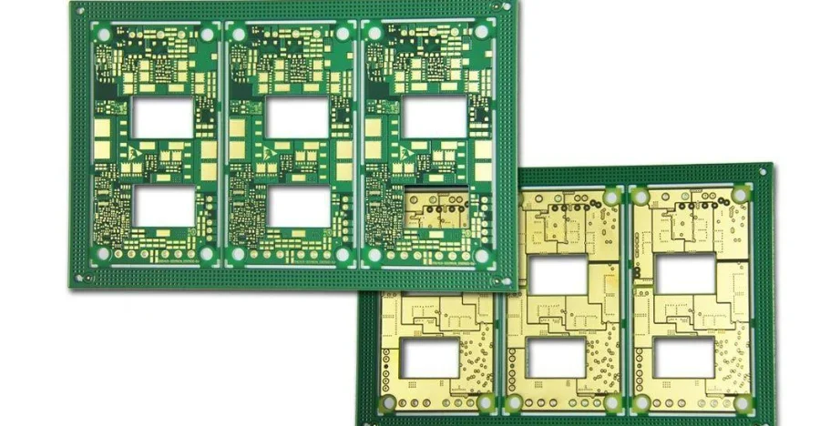
Medical Imaging

Prioritize HDI feasibility, controlled impedance, BGA inspection, high-layer registration, thermal interfaces and coupon evidence.

IVD and Laboratory

Prioritize contamination controls, cleaning limits, motor and heater loads, sensor interfaces and calibration or functional-test access.

Therapeutic Devices

Prioritize safety-critical AVL control, isolation geometry, power-stage inspection, interlocks and customer-defined functional limits.

Wearable and Home Use

Prioritize flex construction, bend zones, battery interfaces, miniaturization, coating zones and enclosure-level environmental validation.

Power and Control

Prioritize working-voltage inputs, creepage and clearance, slots, material control, thermal rise and system-level safety testing.

What Should You Include in a Medical PCB/PCBA RFQ?

A complete RFQ lets engineering identify risk before price and lead-time assumptions become commitments.
Fabrication package:
  • Gerber RS-274X, ODB++ or IPC-2581 plus drill and net data
  • Released drawing, stackup, materials, copper, finish and controlled-impedance requirements
  • IPC class, critical dimensions, coupons and special acceptance criteria
Assembly and test package:
  • BOM with manufacturer part numbers, AVL and approved alternates
  • Centroid data, assembly drawings, polarity and special-process notes
  • Inspection/test method, coverage, limits, fixtures, software and expected report
  • Cleaning, ionic cleanliness, conformal coating and handling requirements
Program controls:
  • Prototype, validation and production quantities
  • Revision, deviation and change-notification rules
  • Lot or board traceability, serialization, labeling and record-retention needs
  • Required CoC, FAI, test, material or other release documents

What Can APTPCB Confirm Before Your First Build?

Before order release, APTPCB can review the supplied PCB and PCBA package for manufacturability, assembly access and testability; identify assumptions or missing acceptance inputs; and confirm which capability limits, inspection steps and documents are included in the quotation.
The useful outcome is a controlled handoff: one approved data revision, a defined material and component basis, an agreed inspection and test scope, and a shipment package that matches your supplier-quality needs. Project-dependent options are quoted as options instead of presented as automatic evidence.
Send the current design package even if validation is not complete. Early DFM and DFT questions are easier to resolve before tooling, component procurement and qualification builds.

Send Your Medical PCB/PCBA Package for DFM Review

Share your fabrication data, BOM, assembly drawings, test scope and documentation requirements. We will confirm feasibility, quote assumptions and the proposed release evidence before build.

Frequently Asked Questions

Is APTPCB ISO 13485 certified?

Do not assume ISO 13485 coverage from this page. APTPCB publishes ISO 9001:2015 and UL quality credentials; request the current certificates and scope during supplier qualification. If your program requires an ISO 13485-approved supplier, state that requirement in the RFQ and complete approval before nomination.

What should a medical PCB or PCBA RFQ include?

Provide fabrication data, stackup and impedance requirements, BOM and approved alternates, assembly drawings, annual and build quantities, acceptance class, inspection and test specifications, cleanliness or coating requirements, traceability level, labeling and the release documents you expect.

Can medical PCBs be built to IPC Class 3?

Yes, when IPC Class 3 is specified and the design, materials, process and inspection plan support it. State the applicable IPC fabrication and assembly criteria in the RFQ; APTPCB confirms feasibility and the required evidence during DFM and quotation.

Which inspection and test records are available for medical PCBAs?

Available controls can include SPI, AOI, X-ray for hidden joints, electrical test, flying probe or ICT, and customer-defined functional test. The exact test method, sampling or coverage, acceptance limits and report format must be agreed before the build.

Does PCB or PCBA manufacturing certify the finished medical device?

No. PCB and PCBA manufacturing can implement agreed drawings, materials, acceptance criteria, traceability and release evidence. Final IEC 60601 performance, risk management, biocompatibility, clinical safety and regulatory approval remain device- and system-level responsibilities of the legal manufacturer.