
01
Material identity
Confirm trade name, construction code, core/prepreg, thickness, glass style, resin content, and copper option. Request a certificate of conformity as a separate deliverable when the project requires it.

High-Speed Digital & RF Laminates
An Isola PCB is a printed circuit board whose laminate and prepreg construction is matched to the loss budget, impedance targets, thermal cycle, and via design. APTPCB fabricates Isola-material boards after reviewing the exact grade, core and prepreg, glass style, copper profile, stack-up, and acceptance evidence. Material selection does not replace channel simulation or end-product qualification.
What the Buyer Is Specifying
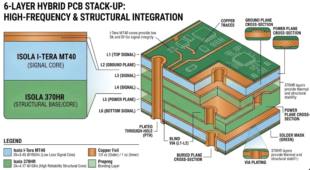
The Isola portfolio addresses different engineering problems. 370HR and FR408HR are thermally robust FR-4 systems with different loss levels; I-Speed and I-Tera MT40 target more demanding high-speed digital and mixed-signal designs; Tachyon 100G and Astra MT77 address ultra-low-loss digital and RF/microwave work. Isola publishes material-specific Dk, Df, Tg, and Td values with defined test conditions.
Material choice must be tied to the core and prepreg construction, glass style, resin content, pressed thickness, copper profile, trace geometry, and via architecture. Materials in a similar loss class are therefore not automatic substitutes. APTPCB confirms the proposed grade, hybrid construction, coupons, and evidence package after reviewing the input files for a high-speed PCB or RF build.
Selection Matrix
Use this matrix to narrow candidates. It does not replace channel analysis, construction availability review, or a released stack-up.
| Material | Isola Positioning | When to Consider It | What to Recheck | RFQ Output |
|---|---|---|---|---|
| 370HR | High-performance 180 °C Tg FR-4 | A multilayer board where thermal reliability, CAF resistance, and a familiar FR-4 process are the priorities | Critical-channel loss, glass styles, finished thickness, and assembly thermal exposure | Confirmed core/prepreg, stack-up, and acceptance criteria |
| FR408HR | Lead-free, mid-loss laminate | Standard high-Tg FR-4 misses the loss budget, but an ultra-low-loss system is unnecessary | Model frequency, construction-specific Dk/Df, copper foil, and impedance geometry | Released stack-up and agreed impedance-coupon plan |
| I-Speed | Low-loss epoxy laminate | A high-speed digital board needs more insertion-loss margin than FR408HR provides | Channel length and topology, connectors, transitions, backdrill, glass weave, and copper profile | Material construction and channel-control points |
| I-Tera MT40 | Very-low-loss laminate and prepreg | A high-speed digital, RF/microwave, or mixed-signal board has a tighter loss budget | Exact Dk option, core/prepreg construction, hybrid boundaries, via architecture, and thermal profile | Fabrication review and a frozen material specification |
| Tachyon 100G | Ultra-low-loss laminate for very high-speed digital | A high-layer-count backplane or daughtercard makes conductor loss, skew, and transitions material to the channel budget | Spread-glass construction, copper profile, etch tolerance, backdrill, and correlation method | Release stack-up, coupon strategy, and evidence list |
| Astra MT77 | Ultra-low-loss RF/microwave laminate | RF, microwave, or mixed-signal sections need low Df with a thermoset material system | Operating frequency, RF geometry, thickness, copper, finish, transitions, and end-assembly qualification | Confirmed construction and project-specific RF/acceptance plan |
Availability of the exact grade, thickness, glass style, resin content, and copper option is confirmed in the RFQ. Alternatives require written approval.
Manufacturer Data
The values below come from current Isola Group product pages. Frequency and method vary by material, so the numbers should not be compared without their test context.
| Material | Dk | Df | Frequency & Method | Tg, °C (DSC) | Td, °C (TGA, 5%) | How to Use the Data |
|---|---|---|---|---|---|---|
| 370HR | 4.04 | 0.021 | 2 GHz; Isola table, Bereskin Stripline | 180 | 340 | Preliminary high-Tg FR-4 comparison; use construction-specific data for impedance modeling |
| FR408HR | 3.68 | 0.0092 | 2 GHz; Isola table, Bereskin Stripline | 190 | 360 | Mid-loss screening; confirm model frequency and resin content for the selected construction |
| I-Speed | 3.63 | 0.0060 | 10 GHz; Isola table, Bereskin Stripline | 180 | 360 | Low-loss digital comparison; include glass-weave and copper-roughness effects |
| I-Tera MT40 | 3.45 | 0.0031 | 2–10 GHz; IPC-TM-650 2.5.5.5 / Bereskin Stripline | 215 | 360 | Starting point for very-low-loss or mixed-signal stack-ups; confirm the selected Dk option |
| Tachyon 100G | 3.02 | 0.0021 | 10 GHz; IPC-TM-650 2.5.5.5 / Bereskin Stripline | 215 | 360 | Preliminary ultra-low-loss digital model; include HVLP copper and transition behavior |
| Astra MT77 | 3.00 | 0.0017 | 10 GHz; IPC-TM-650 2.5.5.5 / Bereskin Stripline | 200 | 360 | RF/microwave candidate comparison; qualify the final geometry at the product frequency |
Source: Isola Group product pages for 370HR, FR408HR, I-Speed, I-Tera MT40, Tachyon 100G, and Astra MT77, accessed July 2026. These are typical values, not guaranteed finished-channel parameters. Check the current datasheet and construction table before release.
Substitution Boundaries
Changing laminate affects more than loss. It can change impedance, trace width, pressed thickness, registration, drilling, copper profile, and assembly qualification.
| Scenario | Why It May Be Considered | Why It Is Not Drop-In | What Must Be Re-Released |
|---|---|---|---|
| 370HR → FR408HR | Lower Df is needed while staying in an FR-4 material family | Dk/Df, Tg, prepreg constructions, and final geometry differ | Stack-up, impedance table, and thermal profile |
| FR408HR → I-Speed | The channel needs additional loss margin | The electrical model, available glass styles, and conductor calculation change | Channel model, trace geometry, and coupon |
| I-Speed → I-Tera MT40 | A tighter insertion-loss budget or mixed-signal layer is required | A specific Dk option must be selected and lamination/via architecture reviewed | Material specification and DFM release |
| I-Tera MT40 → Tachyon 100G | The design requires an ultra-low-loss digital channel | Copper profile, spread glass, thicknesses, and skew control become part of the model | SI model, stack-up, and validation plan |
| Astra MT77 ↔ Rogers / PTFE | The candidates occupy a similar RF/microwave loss class | Resin systems, Dk, copper, thicknesses, transitions, and processes differ | RF geometry, finish, transitions, and qualification coupon |
| Isola / Other-Material Hybrid | Use the higher-cost low-loss material only on critical layers | CTE, flow, cure, bonding interfaces, copper balance, and registration must be aligned | Lamination sequence and every material boundary |
A substitution is accepted only after engineering review and customer approval. A new material name without a new released stack-up is not an engineering release.
Path to Production
The review starts with Gerber or ODB++, drill data, netlist, fabrication drawing, layer count, finished thickness, copper, proposed Isola grade, impedance targets, via requirements, backdrill, and assembly profile. A brand or grade name without the core/prepreg construction is treated as a material preference, not a production-ready specification.
The exact construction codes, glass style, resin content, copper foil, pressed thickness, lamination sequence, and permitted trace corrections are then agreed. For controlled impedance, define the target, tolerance, coupon, measurement method, and report format before release. Hybrid builds, laser vias, filled vias, and sequential lamination remain subject to DFM.
Production receives a frozen package: approved stack-up, material callout, drill/via notes, impedance table, surface finish, customer acceptance criteria, and evidence list. A material or construction change after release requires reapproval. This connects material selection to actual PCB impedance control instead of an abstract low-loss claim.
Release Gate
These seven checkpoints turn a material preference into a repeatable manufacturing specification.
| Checkpoint | Customer Input | Engineering Review | Release Output |
|---|---|---|---|
| 1. Material & substitutions | Exact grade or acceptable shortlist | Available construction, approved alternative, manufacturer revision | Frozen material callout |
| 2. Core / prepreg | Target thickness and layer constraints | Glass style, resin content, pressed thickness, symmetry | Released stack-up |
| 3. Copper | Copper weight and critical RF/high-speed layers | Foil profile, finished copper, etch compensation | Agreed copper construction |
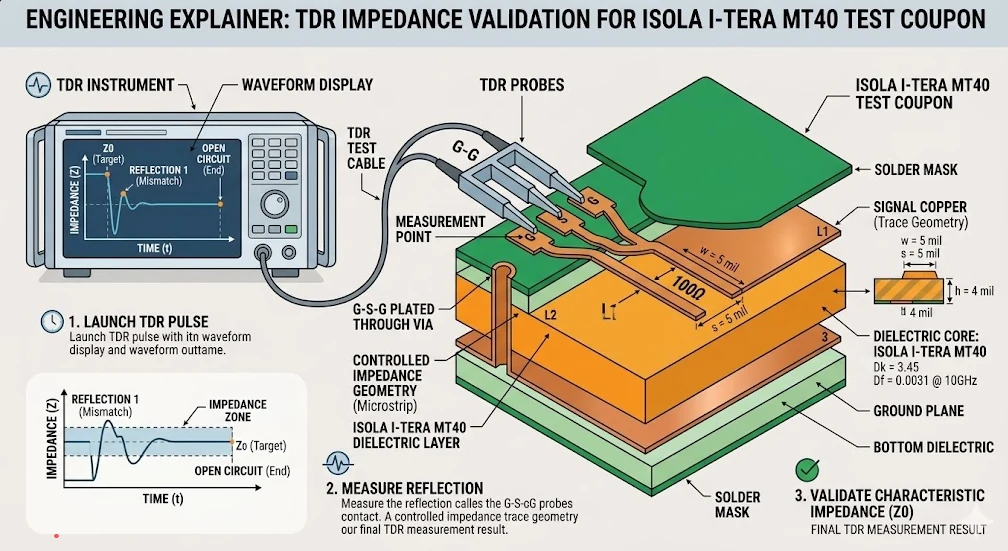
| 4. Impedance & loss | Targets, tolerance, frequency, and channel budget | Geometry, model, coupon, and measurement method | Impedance table and validation plan |
| 5. Via architecture | Drill map, aspect ratio, microvia, filled via, backdrill | Sequence, annular ring, stub, and metallization | Released drill/via notes |
| 6. Assembly exposure | Reflow profile, thermal excursions, high-mass components | Compatibility of material, finish, and construction | Fabrication/assembly constraints |
| 7. Acceptance evidence | Required certificates, coupons, microsections, and reports | Feasibility, sampling, format, and acceptance criteria | Agreed evidence package |
If a critical checkpoint remains open, price and schedule are preliminary. Final commercial and technical conditions are confirmed in the RFQ.
Manufacturing Controls
The exact control plan depends on board complexity and is stated in the technical and commercial proposal.
Confirm trade name, construction code, core/prepreg, thickness, glass style, resin content, and copper option. Request a certificate of conformity as a separate deliverable when the project requires it.
Review symmetry, copper distribution, pressed thickness, sequence, and material boundaries. Hybrid builds require specific review of flow, cure, and registration risk.
Select drill program, aspect ratio, smear-removal route, and metallization for the actual construction. A manufacturer's FR-4-compatible processing statement does not replace board-specific DFM.
Agree trace width/space, finished copper, and permitted geometry adjustment before CAM release. Coupons and tolerances apply only when they are included in the order.
For higher-risk via structures, specify microsection, copper measurements, resin-fill checks, and evaluation criteria. Sampling and report format are agreed in advance.
Preserve the approved stack-up and material callout for repeat orders. Any core/prepreg, copper-option, or construction change requires notification and reapproval.
Evidence and Boundaries
A basic board release demonstrates conformance to the agreed manufacturing data: material callout, stack-up, dimensions, electrical continuity, and the visual criteria in the order. The RFQ can add an impedance coupon, microsection, plating measurement, dimensional report, material certificate, or other records when technically feasible.
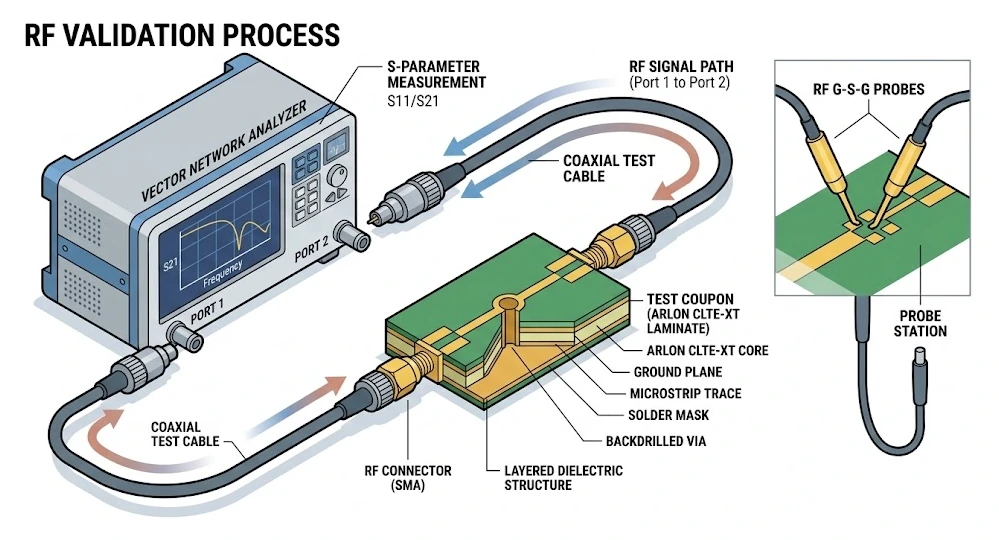
TDR verifies the impedance of the specified coupon. VNA or S-parameter testing verifies only the agreed test vehicle and frequency range. Neither document alone guarantees insertion loss for the complete channel, SerDes operation, antenna performance, or system compliance; correlation also depends on connectors, transitions, launch design, stack-up, copper, length, and the customer's model.
APTPCB is responsible for building to the approved manufacturing package and agreed acceptance criteria. Electrical architecture, system-level compliance, RF/EMC performance, functional safety, and end-product qualification remain the customer's responsibility. Reference documents should be listed by revision in the RFQ, such as the current Isola product datasheet and construction table, IPC-TM-650 2.5.5.5 where applicable, and the project drawing or acceptance specification. Link those requirements to the PCB quality plan before release.
Applications by Engineering Problem
The application suggests a starting point, not guaranteed suitability. Select the material and stack-up from the actual frequency, channel, environment, and qualification plan.
Evaluate FR408HR, I-Speed, I-Tera MT40, or Tachyon 100G against channel length, transitions, backdrill, connectors, skew, and copper profile.
Choose by loss budget and layer assignment. RF and digital sections may require different constructions and separate release decisions.
Consider Astra MT77 or I-Tera MT40 with operating frequency, geometry, copper foil, transitions, finish, and the measurement plan.
Isola publishes Astra MT77 material guidance for automotive radar use. The customer qualifies the complete module under the applicable product program.
Repeatable impedance, loss correlation, connector launch, and a documented test vehicle matter more than the laminate's headline Df alone.
Shortlist 370HR, FR408HR, or a low-loss family from the combined thermal profile, interconnect density, and signal-integrity requirements. System qualification remains with the product owner.
Practical Selection
Five engineering decisions and one complete RFQ package are more useful than choosing only by the lowest published Df.
State channel length, topology, model frequency range, transitions, connectors, allowable insertion loss, and return loss. The same interface can require different materials when length or via architecture changes.
Tg and Td help compare families, but reliability also depends on Z-axis expansion, via design, lamination count, and assembly profile. An ultra-low-loss material is not automatically a thermal-reliability solution.
Define single-ended/differential targets, tolerance, reference planes, and permitted CAM correction. Model with the selected construction's Dk, not a single headline value from a product page.
List approved grades and prohibit unreviewed substitution. For a hybrid, assign each material by layer and define thickness and registration constraints.
Specify whether the project needs a material certificate, impedance coupon, microsection, plating measurement, dimensional report, or S-parameter test vehicle. A report not included before fabrication may be impossible to add later.
Attach Gerber or ODB++, drill data and IPC-356 netlist, fabrication drawing, layer count, finished thickness, copper, preferred Isola grade and approved alternatives, stack-up or stack-up constraints, impedance table, via/backdrill notes, surface finish, panel/quantity, assembly profile, and required acceptance records. For a hybrid board, identify the material assigned to each layer.
FAQ
Quick Shortlist
Typical manufacturer data helps identify candidates; the exact construction and fabrication fit are confirmed in the RFQ.
International RFQs
For an international project, agree measurement units, applicable specifications, material certificates, export constraints, packaging, and logistics before release. Commercial terms remain RFQ-specific.
State the applicable customer-standard revisions, units, certificate format, and traceability requirements before order release.
Freeze manufacturer and grade, approved substitutions, construction revision, and the notification path for changes.
Provide Gerber/ODB++, drill data, netlist, impedance table, and fabrication drawing in the agreed units and coordinate system.
Confirm ship-to address, Incoterms, packaging, export constraints, and the required shipment-document set before ordering.
Upload the manufacturing files, material preference, stack-up constraints, impedance table, and required evidence. We will review the construction and return an RFQ with confirmed material options, process boundaries, and acceptance deliverables.