Copper plating process during printed circuit board fabrication

From CAM review to bare-board release

PCB Fabrication Process: Steps, Risks and Release Evidence

PCB fabrication transforms an approved design package into a bare printed circuit board through CAM/DFM review, material preparation, imaging, lamination, drilling, metallization, solder mask, surface finish, profiling, and electrical test. Before the build starts, buyer and manufacturer should agree the stack-up, materials, tolerances, controls, acceptance criteria, and release documents. Actual capabilities, sampling, records, and timing depend on the released design and order.

DFM / CAM
One approved data baseline
Process controls
Risk tied to evidence
Release package
Defined for the order

Get an Instant Quote

Full Quote →
Gerber / ODB++ / IPC-2581Identified fabrication dataset
Stack-up and materialsApproved before build
DFM / CAMChanges require authorization
AOI and dimensionsCoverage follows control plan
E-test and couponsLimits agreed by order
Lot documentationDeliverables defined in RFQ
Gerber / ODB++ / IPC-2581Identified fabrication dataset
Stack-up and materialsApproved before build
DFM / CAMChanges require authorization
AOI and dimensionsCoverage follows control plan
E-test and couponsLimits agreed by order
Lot documentationDeliverables defined in RFQ

Stage 1 · Data and feasibility

PCB fabrication starts with decisions, not silent CAM edits

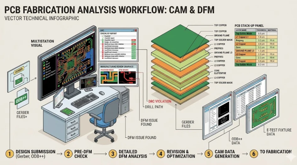
CAM converts the customer's released design into production artwork, drill programs, tooling, coupons, and panel instructions. DFM review checks consistency across copper, solder mask, legend, drill, profile, netlist, stack-up, and fabrication drawing; it also identifies geometry, registration, copper balance, panelization, or special-process risks before material is committed.

Buyer input
State revision, units, finished board dimensions, stack-up proposal, finished copper, finished hole sizes, tolerances, controlled-impedance structures, surface finish, mask, marking, panel delivery, test coverage, applicable standards, and required reports. Use the PCB stack-up guide and controlled-impedance guide to make critical requirements explicit.

Approval boundary
The manufacturer should return questions that change geometry, netlist, material, panel, test method, or acceptance criteria. Record every approved deviation and release one manufacturing baseline. Procurement, design, quality, and the fabricator can then evaluate the same product instead of reconciling assumptions after the build starts.

CAM and DFM review of PCB fabrication data before production release

Stage 2 · Technical baseline

Eight decisions to close before material and tooling are committed

This release matrix separates customer intent from manufacturing verification and the evidence needed to keep the order controlled.

DecisionCustomer inputFabrication reviewRelease evidence
Data package and revisionGerber, ODB++, or IPC-2581; drill; netlist; drawing; units; revisionLayer mapping, polarity, scale, drill spans, profile, netlist, and drawing consistencyReleased dataset and resolved CAM question log
Stack-up and layer functionLayer count, finished thickness, planes, critical signals, and dielectric constraintsBuildable construction, core and prepreg availability, symmetry, and resin flowApproved stack-up with revision
Base materialsMaterial family or specification, relevant properties, and substitution rulesAvailable construction, process compatibility, and laminate supplier dataApproved material and permitted alternatives
Starting and finished copperRequired copper weight or thickness by layer and any selective areasEtch, plating, spacing, thermal balance, and finished-thickness effectsFinished-copper table and CAM notes
Controlled impedanceTarget, tolerance, structure, layer, reference plane, and report requirementModel against the proposed stack-up, allowable CAM adjustment, and representative couponApproved impedance table and verification plan
Holes and via architectureFinished size, plated or non-plated status, blind/buried/microvia/backdrill spans, and tolerancesDrill method, aspect ratio, registration, fill, planarization, and lamination sequenceReleased tool table and via-structure map
Mask, finish, profile, and panelOpenings, keep-outs, finish, edge contacts, dimensions, array, breakaways, fiducials, and markingCompatibility with fabrication, assembly, handling, profiling, and delivery formatApproved fabrication and panel drawings
Inspection, test, and documentsAcceptance standard, class, exceptions, sampling, tests, reports, traceability, and retentionApplicable methods, representative samples, data format, and order-specific availabilityControl plan and release-document list

If a choice changes process route, cost, risk, or schedule, close it before production authorization and record it in the order baseline.

Stages 3–8 · Inner layers and lamination

From released CAM data to a laminated multilayer panel

Each step has a dominant failure mode and a release signal. The exact equipment and parameters depend on the material system and construction.

01

CAM preparation and panelization

Action: generate production artwork, tooling, drill programs, coupons, and panel instructions from the released dataset. Risk: revision, polarity, scale, layer-order, or netlist mismatch. Evidence: CAM checklist and comparison plots when required by the approved workflow.

02

Inner-layer imaging and etching

Action: transfer the circuit pattern to copper, develop the resist, and remove unwanted copper. Risk: over-etch, residue, undercut, or variation that changes trace and space geometry. Evidence: process checks and agreed measurements on critical features.

03

Inner-layer AOI

Action: compare the physical inner-layer image with CAM data before the layer is buried. Risk: opens, shorts, foreign copper, or geometry defects surviving into lamination. Evidence: inspection status and documented disposition of detected anomalies.

04

Bond preparation and lay-up

Action: prepare copper surfaces and stack cores, prepreg, and foil in the approved sequence. Risk: wrong material, orientation error, contamination, or insufficient resin distribution. Evidence: material identification and lot-linked lay-up record.

05

Multilayer lamination

Action: consolidate the stack with a cycle matched to the construction and resin system. Risk: voids, delamination, thickness variation, or registration outside the agreed limit. Evidence: cycle records and post-lamination checks defined by process control.

06

Post-lamination registration

Action: locate internal targets and verify thickness, panel condition, and alignment before drilling. Risk: annular breakout or insufficient connection to inner layers. Evidence: measurements, coupons, or microsections when required by the drawing or control plan.

Stage 9 · Vertical interconnects

Mechanical, laser, and controlled-depth drilling need different release data

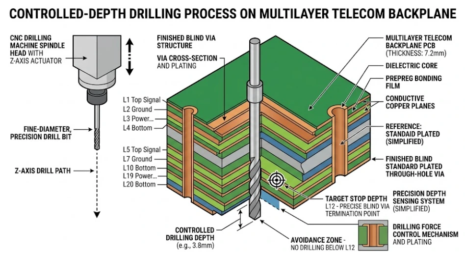
Drilling creates plated through holes, non-plated holes, slots, and via structures. Microvias and some blind or buried via builds can require laser drilling and sequential lamination. Backdrilling adds a depth relationship to the connected layer. The process cannot be selected from nominal hole diameter alone; it depends on the complete stack-up and connection structure.

DFM risks to close
Ambiguous finished versus tool diameter, drill-to-copper clearance, aspect ratio, registration, via span, fill, planarization, and backdrill depth can change feasibility and cost. Put these requirements in the fabrication drawing and drill legend. See the PCB drilling guide for the inputs that should accompany an RFQ.

Release evidence
The tool table, via map, backdrill rules, finished dimensions, and verification method should match the approved revision. Dimensional results, microsections, or coupons are included only when the drawing, control plan, or order calls for them.

Controlled-depth drilling during printed circuit board fabrication

Stages 10–11 · Hole preparation and copper

Desmear and metallization turn a drilled hole into an electrical interconnect

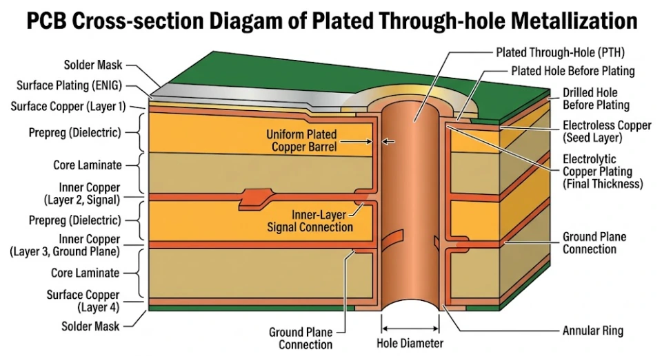
After drilling, the hole wall must be cleaned and conditioned so inner-layer copper is correctly exposed. Desmear and surface-treatment chemistry must suit the dielectric system; one recipe does not fit every FR-4, high-speed, RF, or flexible material.

Deposition and electroplating
An initial conductive deposit makes the hole wall plateable, then electroplating builds copper to the requirement defined by the drawing and applicable specification. Current distribution, panel geometry, agitation, and solution control influence uniformity, particularly in the most demanding holes in the build.

Risk and evidence
Resin residue, voids, interconnect separation, or insufficient copper can affect continuity and thermal-cycle endurance. Verification may include process records, thickness measurement, and microsectioning with agreed sampling and acceptance limits. IPC-6012 is a qualification and performance specification for rigid printed boards; class, revision, exceptions, and applicability must be stated in the order rather than inferred from a marketing claim.

Cross-section of a plated through hole in a multilayer printed circuit board

Stages 12–16 · Outer layers and protection

From outer-layer imaging to a board ready for final verification

These stages preserve electrical geometry while preparing pads, mask, markings, and mechanical features for assembly and controlled delivery.

Outer circuitry

Imaging, pattern plating, and etching

Action: form outer-layer traces, pads, and copper features with the approved CAM sequence. Risk: width variation, undercut, shorts, or residual copper. Evidence: dimensional checks and inspection on the features and sampling defined by the control plan.

Protection

Solder mask and legend

Action: apply, image, develop, and cure solder mask, then add required identification. Risk: pad encroachment, unbuildable mask dams, contamination, or ambiguous marking. Evidence: openings and text checked against released data and order criteria.

Assembly interface

Surface finish

Action: protect exposed copper with the selected finish. Risk: planarity, soldering, contact, bonding, RF, or storage needs not matching the chosen finish. Evidence: finish type, selective areas, and agreed checks stated in the drawing. Compare PCB surface finishes.

Mechanical delivery

Profiling, cleaning, and identification

Action: machine the profile, slots, and edges, clean the board, and apply required codes. Risk: dimensions outside tolerance, burrs, edge damage, contamination, or unreadable identity. Evidence: dimensional, visual, cleanliness, and marking status required by the release plan.

Surface-finish decision

Choose a PCB surface finish from the assembly and product interface

The correct finish depends on pad geometry, assembly process, contact function, storage, handling, regulatory scope, and the fabricator's qualified process.

FinishWhy it may be selectedTrade-offs to reviewConfirm in the RFQ
Lead-free HASLCost-sensitive solderable boards where its surface profile is acceptablePlanarity and thermal exposure may not suit every fine-pitch designAlloy, thickness expectations, pad geometry, and assembly compatibility
ENIGFlat solderable surface and exposed-pad protection for many assembly flowsNickel layer, process control, contact use, and RF loss must be evaluated by applicationApplicable finish specification, nickel/gold requirements, and selective areas
ENEPIGProjects combining soldering with compatible wire-bonding or contact requirementsMore process steps and cost; bonding performance depends on the complete interfaceBonding method, finish stack, pad use, and acceptance method
Immersion silverFlat finish where solderability or RF behavior supports the design choiceHandling, packaging, environment, and storage controls require alignmentThickness requirement, packaging, storage window, and assembly timing
Immersion tinFlat solderable finish for a compatible assembly and storage planProcess compatibility, handling, and storage expectations must be controlledApplicable specification, thickness, packaging, and assembly exposure
OSPThin, flat protection for copper when the assembly sequence supports itMultiple thermal cycles, handling, inspection, and contact use need reviewChemistry, assembly cycles, storage, packaging, and exposed-contact exclusions

Do not select a finish from a universal ranking or an assumed shelf life. Confirm the specification, thickness or process requirement, packaging, storage, and intended interface for the actual order.

Inspection, test, and release

Quality evidence should answer a defined acceptance question

AOI, measurement, electrical test, coupons, and documents serve different purposes. No single check proves every aspect of the finished product.

01

AOI and visual inspection

Action: compare relevant circuitry, mask, finish, and workmanship with released data and applicable criteria. Risk: assuming optical inspection detects hidden or electrical defects. Evidence: inspection status and anomaly disposition under the control plan.

02

Dimensional verification

Action: measure profile, holes, slots, thickness, and identified critical dimensions. Risk: using unspecified tolerances or nonrepresentative sampling. Evidence: measured results or inspection record when required by the order.

03

Bare-board electrical test

Action: test continuity and isolation against the supplied netlist and agreed limits. Risk: treating an e-test pass as functional validation of an assembled product. Evidence: status or report in the agreed format.

04

Controlled-impedance coupon

Action: measure a representative coupon when impedance verification is part of the order. Risk: coupon structure, test method, or acceptance limit not matching the routed design. Evidence: target, measured result, method, and coupon relationship defined in the plan.

05

Microsection and metallography

Action: examine representative plated-hole, via, or layer structures when required. Risk: drawing conclusions from an undefined location or sample. Evidence: section location, preparation method, sampling, criteria, and results tied to the lot.

06

Document and shipment release

Action: reconcile revision, quantity, marking, deviations, test status, packaging, and required records. Risk: shipping acceptable boards with incomplete or mismatched documentation. Evidence: the release package listed in the purchase order.

Buyer, design, and quality checklist

Five release gates from RFQ to shipment

Use these gates to keep critical requirements explicit across quotation, DFM, production authorization, process changes, and final release.

RFQ gate · Can the supplier quote the same PCB you intend to build?

Include copper, mask, legend, drill, profile, netlist when available, stack-up, fabrication drawing, quantity, materials, via structures, impedance targets, finish, tolerances, panel delivery, test coverage, acceptance standards, marking, packaging, and documents. Identify revision and priority. An incomplete package produces assumptions, not a production baseline.

DFM closure · Has every product-defining change been approved?

Record DFM questions, approved CAM edits, material alternatives, panel rules, coupons, test methods, and deviations. The stack-up, drill plan, and controlled-impedance plan must all reference the same released dataset.

Production authorization · Does the purchase order match the technical baseline?

Confirm quantity, revision, stack-up, materials and substitution rules, performance class, tolerances, surface finish, tests, sampling, pilot or first-article requirements, release documents, and deviation authority. Price and schedule apply to this scope, not to a generic supplier capability statement.

Change-control gate · Will a prototype-to-production change trigger revalidation?

Define which changes require notice and approval: laminate or prepreg, copper construction, stack-up, via sequence, panelization, finish process, test method, production site, tooling, or acceptance sampling. State which evidence must be repeated before the revised build is released.

Shipment release · Do the records prove the ordered requirements?

IPC-2221C covers generic printed-board design requirements; IPC-6012E addresses qualification and performance for rigid printed boards; IPC-A-600K provides printed-board acceptability criteria; IPC-9252B covers electrical testing of unpopulated boards; IPC-SM-840E addresses permanent solder-mask qualification and performance; IPC-2581 defines manufacturing-data exchange. IPC-TM-650 contains test methods that may be invoked by a specification or order. Confirm revision, class, method, exceptions, and responsibility in the contract: naming a standard alone does not prove certification or compliance.


Questions before order release

PCB Fabrication Process FAQ

What files are needed to start PCB fabrication?
Provide copper, solder mask, legend, drill, and profile data in Gerber, ODB++, or IPC-2581; a fabrication drawing; stack-up; netlist when available; and requirements for materials, finished copper, finished holes, impedance, surface finish, tolerances, testing, marking, and documents. Identify the released revision and units.
Is Gerber still suitable for PCB manufacturing?
Yes. Ucamco describes Gerber as the de facto standard for PCB design-data transfer. Gerber layer files can represent copper, solder mask, legend, drill, and route data, while attributes and a Gerber Job file can add manufacturing metadata. ODB++ and IPC-2581 are also useful when both parties can exchange and verify the richer dataset.
What must the customer approve before production starts?
Close all DFM questions that affect geometry, netlist, stack-up, material or approved substitutions, finished hole sizes, tolerances, impedance, surface finish, panel delivery, test coverage, acceptance criteria, and release documents. Production should reference one released dataset and a recorded list of approved deviations.
How should a PCB material or laminate substitution be handled?
Evaluate the proposed material against the actual stack-up, electrical and thermal requirements, assembly exposures, thickness targets, copper construction, mechanical constraints, and availability. A similar datasheet headline does not prove equivalence. The allowed substitution rule and approval owner should be stated in the order.
Does bare-board electrical testing prove the PCB will work in the product?
No. Bare-board electrical test checks continuity and isolation against the supplied netlist and agreed limits. It does not validate power behavior, firmware, signal integrity, component operation, or system performance. Those checks require a separate PCBA or product-level validation plan.
Which PCB quality reports can be supplied with an order?
Depending on applicability and agreement, the release package may include a certificate of conformance, material references, electrical-test status or report, dimensional results, impedance results, microsection or coupon evidence, and approved deviation records. Define the content, sampling, format, and retention requirement in the RFQ.
How is the right PCB surface finish selected?
Select the finish from assembly method, pad geometry, planarity, contact or wire-bonding needs, RF sensitivity, storage conditions, handling, regulatory requirements, cost, and supplier process compatibility. No finish is universally best, and shelf-life or thickness expectations should be confirmed for the actual specification and order.
What determines PCB fabrication price and lead time?
The main drivers are stack-up, material availability, quantity, panel utilization, copper weight, via architecture, sequential lamination, tolerances, surface finish, testing, documentation, and unresolved DFM questions. A reliable quote requires the complete technical package and a defined production scope.

Controlled collaboration across locations

One released PCB baseline for distributed teams

Time zone, language, and logistics may change, but revision, approvals, deviations, acceptance criteria, and release evidence should remain traceable in the order package.

North America
NPI and production-transfer programs

Separate the product baseline from a previous supplier's internal process assumptions, then approve material, panel, tooling, test, and documentation equivalence before transfer.

NPIChange controlRelease evidence
Europe
Specification-led sourcing

Identify the applicable drawing, standard revision, customer exceptions, material rules, and required records so quotation and acceptance use the same criteria.

SpecificationsApproved deviationsOrder records
Asia-Pacific
Material and production coordination

Align material availability, authorized alternatives, data format, build sequence, inspection plan, and delivery terms before confirming production scope.

MaterialsDFMControl plan
Global programs
A shared dataset across functions

Design, procurement, quality, and manufacturing teams should reference one released revision with named owners for approvals and deviation decisions.

Single baselineApproval ownersTraceability

Is your PCB package ready for fabrication review?

Send fabrication data, drill files, stack-up, drawing, quantity, and test requirements. We will scope the quote and DFM questions against the actual build rather than a generic capability list.

Contact the Engineering Team