
01
Material identity drift
Failure mode: family name replaces the exact part number or revision.
Control: freeze manufacturer, grade, construction, copper and alternate policy in the RFQ.
Taconic RF & Microwave Materials
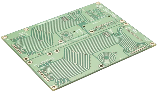
A Taconic PCB is an RF or microwave circuit board that uses a specified Taconic laminate or bonding material within a controlled dielectric stack. This page helps engineers compare published typical values without mixing test methods, define fabrication-sensitive inputs, and release a quotation package that distinguishes material data from board-level capability.
Engineering Definition
Taconic is a portfolio, not a single interchangeable substrate. TLY, TLX, RF, TSM, CER and fastRise products use different compositions and published data contexts. The buyer therefore needs to specify the exact material designation and revision, then connect it to the stack-up, copper system, frequency range and acceptance plan.
The practical value of this page is decision control: it separates manufacturer-published typical values from values that must be confirmed by the current data sheet, field solver, DFM review or board-level test. For adjacent PTFE process considerations, see PTFE PCB fabrication.
Material Selection Matrix
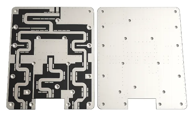
Use this as a shortlist, not a substitution table. Compare adjacent Rogers RF laminates, then confirm the current manufacturer data sheet, intended copper construction and board-level model.
| Family | Shortlist when | Published signal | Design trade-off | RFQ input |
|---|---|---|---|---|
| TLY-5A / TLY-5 | Insertion loss is the first constraint and a low-Dk PTFE-glass construction is acceptable. | Dk 2.17 or 2.20; Df 0.0009 at 10 GHz in the referenced guide. | Low Dk increases line width for a target impedance; PTFE construction affects fabrication planning. | Exact grade, thickness, copper designation, impedance table and loss target. |
| TLX family | A moderate Dk of 2.45–2.65 is useful for size and routing trade-offs. | Published family Df range 0.0015–0.0021 at 10 GHz. | Family-level ranges cannot replace model-specific data. | Exact TLX model, data-sheet revision and modeled Dk. |
| TSM-26 / 29 / 30 | Ceramic-filled PTFE with Dk options around 2.60–3.00 supports a balanced RF design. | TSM-30: Dk 3.00 and Df 0.0013 at 10 GHz in the referenced guide. | The selected grade changes geometry and loss; do not collapse the family to one value. | Grade, thickness, foil, frequency band and thermal constraints. |
| RF-30 / RF-35 / RF-35A2 | A ceramic-filled PTFE-glass laminate around Dk 3.00–3.50 is under consideration. | RF-35: Dk 3.50 and Df 0.0018 at 1.9 GHz; RF-35A2 also publishes Df at 10 GHz. | Test frequency and method differ from TLY data; nominal Dk alone does not support substitution. | Exact suffix, current data sheet, stack-up and validation plan. |
| TLC family | A PTFE-glass option in the published Dk 2.75–3.50 family range merits evaluation. | Published family Df range 0.0023–0.0037 at 10 GHz. | Loss varies by grade; a family range is insufficient for a solver. | Exact TLC grade and current model-specific values. |
| CER-10 | High Dk is being used to reduce resonator, filter or antenna dimensions. | Dk 10.00 by full-sheet resonant method; Df 0.0035 at 10 GHz. | Miniaturization increases sensitivity to tolerance, geometry and test correlation. | Resonant structure, frequency, thickness tolerance and qualification coupon. |
| fastRise 27 | A low-loss thermoset prepreg is needed as part of a multilayer bonding strategy. | Dk 2.70 and Df 0.0014 at 10 GHz in the referenced guide. | Bonding material changes resin content, pressed thickness and impedance; it is not merely an adhesive label. | Pressed-thickness target, copper removal, press construction and impedance model. |
Selection-guide values are typical, not specification limits. Confirm the current Taconic data sheet and availability for the exact part number before design release.
Published Data With Context
The reference below is drawn from a Taconic Advanced PCB Materials Product Selection Guide. It deliberately keeps method and frequency beside each value because cross-method comparisons can be misleading.
| Material | Composition | Published typical Dk | Published typical Df | Test context | Selection implication |
|---|---|---|---|---|---|
| TLY-5A | PTFE / glass | 2.17 | 0.0009 | IPC-TM-650 2.5.5.5 stripline resonator at 10 GHz. | Loss-driven low-Dk shortlist; use current lot and model data for final modeling. |
| TLY-5 | PTFE / glass | 2.20 | 0.0009 | IPC-TM-650 2.5.5.5 stripline resonator at 10 GHz. | Close to TLY-5A in the guide, but still a distinct material callout. |
| TLX-0 / 6 / 7 / 8 / 9 | PTFE / glass | 2.45–2.65 | 0.0015–0.0021 | Dk: IPC-TM-650 2.5.5.5 at 10 GHz; Df: 2.5.5.5.1 modified stripline at 10 GHz. | Select the exact grade before impedance or loss simulation. |
| TSM-30 | PTFE / ceramic / glass | 3.00 | 0.0013 | IPC-TM-650 2.5.5.5.1 modified stripline at 10 GHz. | Balanced Dk and loss candidate; confirm grade and construction. |
| RF-30 | PTFE / ceramic / glass | 3.00 | 0.0014 | IPC-TM-650 2.5.5.5.1 modified stripline at 1.9 GHz. | Do not compare directly with 10 GHz values without a compatible model. |
| RF-35 | PTFE / ceramic / glass | 3.50 | 0.0018 | IPC-TM-650 2.5.5.5.1 modified stripline at 1.9 GHz. | Treat a material change as a re-modeling and qualification event. |
| RF-35A2 | PTFE / ceramic / glass | 3.50 | 0.0016 at 1.9 GHz; 0.0017 at 10 GHz | Dk and first Df: IPC-TM-650 2.5.5.5.1 at 1.9 GHz; second Df: the same modified stripline method at 10 GHz. | Useful example of why frequency must remain attached to Df. |
| CER-10 | PTFE / ceramic / glass | 10.00 | 0.0035 | Dk: IPC-TM-650 2.5.5.6 full-sheet resonant method; Df: 2.5.5.5 stripline resonator at 10 GHz. | High-Dk geometry must be correlated to the chosen model and coupon. |
| fastRise 27 | Thermoset prepreg | 2.70 | 0.0014 | IPC-TM-650 2.5.5.5.1 modified stripline at 10 GHz. | Pressed thickness and resin distribution belong in the stack-up model. |
These are manufacturer-published typical values from the referenced selection guide, not guaranteed board values. Obtain the current Taconic data sheet, procurement construction and applicable tolerance before release.
Substitution Control
RF-35 may enter the same design conversation as other Dk 3.5-class RF laminates, but nominal dielectric constant does not establish equivalence. Use the Rogers material reference for a controlled comparison before changing material.
| Decision point | RF-35 review | Existing-material review | Required release action |
|---|---|---|---|
| Dielectric data | Use RF-35 values with their published method and frequency. | Identify the method, frequency and design Dk used by the existing model. | Re-run the field solver with comparable inputs. |
| Resin and process route | Confirm the exact RF-35 construction and fabricator route. | Document the current laminate chemistry and hole-wall preparation. | Close process compatibility during DFM. |
| Copper interface | Specify foil designation or an agreed roughness model. | Capture the existing copper profile and loss model. | Recalculate conductor loss and impedance. |
| Thickness and stack-up | Use available core construction and tolerances for the exact part number. | Preserve finished thickness and dielectric targets where required. | Issue a controlled stack-up, not a material-name swap. |
| Impedance and phase | Model trace geometry, solder mask and plating effects. | Retain the electrical targets and reference planes. | Approve revised geometry and coupon limits. |
| Thermal and reliability | Define assembly exposure, via structure and environmental needs. | Identify the evidence behind the qualified baseline. | Repeat the risk-relevant qualification evidence. |
| Change control | Record manufacturer, grade, revision and approved construction. | Identify which product records and approvals are affected. | Treat substitution as an engineering change with customer approval. |
A material comparison can support a shortlist; only the customer's re-analysis and qualification can approve a product substitution.
Fabrication Planning
Fabrication planning starts with identity: manufacturer, exact grade, nominal construction, copper, thickness and current data-sheet revision. The fabricator then maps those inputs to drilling, hole-wall preparation, lamination, imaging, etching and surface-finish controls appropriate to the selected material and board design.
For controlled impedance, the released geometry should use the agreed dielectric model, copper thickness and roughness assumption. Coupon design, measurement method, target and tolerance belong in the drawing or purchase specification; TDR, VNA or functional RF evidence is supplied only when explicitly quoted and defined.
Hybrid Taconic and FR-4 constructions require an integrated review of pressed thickness, resin flow, CTE interaction, symmetry, via structure and assembly exposure. The fabricator can close manufacturability, but final product qualification remains the customer's responsibility.
Architecture Decisions
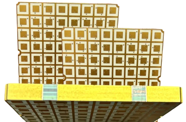
These patterns frame the questions a buyer should close; they are not pre-approved constructions or fixed press recipes. Use the PCB stack-up guide to release the layer definition.
| Architecture | Material role | Must be defined | Dominant risk | Release evidence |
|---|---|---|---|---|
| Two-layer microstrip | Taconic core carries the RF trace and reference plane. | Core grade, thickness, foil, finish, impedance and board support. | Warpage, handling and etch geometry can dominate a thin construction. | Controlled drawing plus dimensional and electrical acceptance plan. |
| Multilayer stripline | Taconic core and bonding layers set embedded-line fields. | Core/prepreg identity, pressed thickness, symmetry and reference planes. | Resin distribution and layer registration change impedance. | Released stack-up and impedance coupon definition. |
| Hybrid RF / FR-4 | Taconic is limited to RF layers while FR-4 carries digital or structural layers. | Both laminate families, bonding material, lamination sequence and via path. | CTE and press compatibility can couple mechanical and electrical risk. | DFM closure of the complete construction. |
| High-Dk resonant structure | CER-10 supports size reduction in a resonator, filter or antenna region. | Frequency, geometry, material thickness, tolerance and tuning strategy. | Small dimensional or Dk variation can shift resonance. | Correlated model and customer-defined RF coupon or functional test. |
| Low-loss feed network | TLY or another selected low-loss grade carries long RF paths. | Insertion-loss budget, copper model, launch geometry and finish. | Conductor roughness and transition loss may erase laminate gains. | Loss model plus agreed coupon or test-vehicle plan. |
| Metal-backed RF board | A Taconic circuit layer is combined with a thermal or structural backing. | Bond interface, metal, flatness, grounding, assembly and thermal path. | CTE mismatch and bond integrity require design-specific validation. | Approved build drawing and thermal/mechanical acceptance criteria. |
Coupled Failure Modes
The highest-risk errors cross material, design and fabrication boundaries. Each control needs an owner and a visible closure record.
Failure mode: family name replaces the exact part number or revision.
Control: freeze manufacturer, grade, construction, copper and alternate policy in the RFQ.
Failure mode: Dk or Df values from different methods are compared as if equivalent.
Control: retain method, frequency and design-value source in the simulation record.
Failure mode: field solving assumes smooth copper while procurement changes foil construction.
Control: name the foil or approve a roughness model and re-analysis rule.
Failure mode: drill, hole-wall preparation or lamination is copied from another material family.
Control: require the fabricator to close the exact process route during DFM.
Failure mode: the coupon does not reproduce the board stack, geometry or reference structure.
Control: release coupon artwork, method, limits and correlation intent with the board.
Failure mode: availability pressure triggers a nominal-Dk swap.
Control: prohibit unapproved alternates and define the customer approval evidence for any change.
Evidence, Not Assumptions
A useful acceptance package begins with the customer drawing and purchase specification. Depending on the board, it may call for material identity, stack-up verification, dimensional results, microsection, electrical test, impedance coupon data or a customer-defined RF test vehicle. Align these records with the PCB quality plan, including sampling and acceptance limits.
Common reference documents include IPC-2221 for generic design principles, IPC-6012 for rigid-board performance requirements, IPC-A-600 for visual acceptability and relevant IPC-TM-650 test methods. These references do not create automatic Class 3, certification or test coverage; the applicable revision and acceptance class must be specified by the buyer and accepted in the quotation.
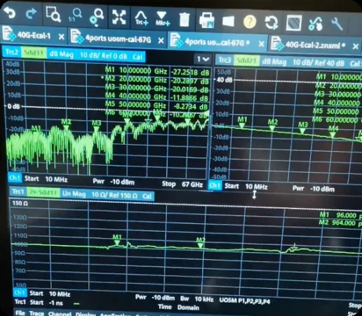
For S-parameter, insertion-loss, phase or functional RF evidence, define fixture, launch, calibration plane, frequency sweep, sample count and pass/fail limits. An instrument name alone does not make a result comparable. The evidence plan should answer what decision the measurement will release.
RFQ and Release Gate
A quote is decision-ready when each row has a buyer input, a DFM closure and an agreed piece of release evidence. This is especially important during NPI and pilot builds.
| Release gate | Buyer input | DFM closure | Release evidence |
|---|---|---|---|
| 1. Material definition | Manufacturer, exact grade, revision, core/prepreg construction and approved alternates. | Availability and process route are confirmed for that construction. | Controlled material callout and supplier acknowledgement. |
| 2. Stack-up and copper | Finished stack, dielectric thicknesses, copper weights, foil designation or roughness model. | Pressed thickness, plating contribution and symmetry are reviewed. | Fabricator stack-up approved by the buyer. |
| 3. Artwork and mechanics | Gerber or ODB++, drill data, drawing, outline, via structures and critical dimensions. | Registration, annular ring, routing and handling risks are closed. | DFM issue log with blocking items resolved. |
| 4. RF performance | Frequency range, impedance table, loss/phase targets, launch definition and solver assumptions. | Geometry and coupons are correlated to the released stack. | Impedance or RF test plan with method and limits. |
| 5. Reliability and assembly | Assembly profile, thermal environment, cycles, mechanical loads and product qualification needs. | Material and via construction are checked against the use case. | Agreed microsection, thermal or customer qualification evidence. |
| 6. Acceptance and deliverables | IPC class or customer criteria, sampling, reports, traceability and packaging requirements. | Feasible inspection coverage and exclusions are stated. | Quotation and drawing list every supplied record and acceptance limit. |
Application Decision Patterns
The application does not select the material by itself. It identifies the dominant risk and the evidence that belongs in the RFQ, including geometry and coupon correlation for an antenna PCB.
Dominant risk: resonance and phase shift from dielectric, thickness and etch variation.
RFQ evidence: exact material, copper, tolerance model and antenna or coupon correlation plan.
Dominant risk: frequency shift and excess loss in narrowband geometry.
RFQ evidence: resonator dimensions, finish, loss model and customer-defined RF limits.
Dominant risk: thermal path, grounding and transition loss around active devices.
RFQ evidence: heat-flow assumptions, copper/backing definition and assembly exposure.
Dominant risk: phase, environmental and documentation requirements that exceed a generic PCB callout.
RFQ evidence: system-specific qualification, material-control and reporting plan.
Dominant risk: launch, antenna and transmission-line correlation across the operating band.
RFQ evidence: calibrated reference plane, sweep range and pass/fail criteria.
Dominant risk: coupled lamination, CTE, via and impedance behavior across dissimilar materials.
RFQ evidence: full hybrid stack, bonding material, press assumptions and DFM closure.
Engineering Shortlist
A defensible selection uses an ordered decision: electrical need, manufacturable construction, evidence plan and controlled procurement.
Use frequency, impedance, insertion loss, phase stability and physical size to define the design window. A low Df may matter for a long feed, while a higher Dk may matter more for a compact resonator. Do not choose from Dk alone.
Keep test method and frequency attached to every published value. If the simulation requires design Dk, dispersion or a copper roughness model, obtain the appropriate current data rather than substituting a catalog typical value.
Choose the exact core, prepreg or bonding construction with the fabricator. Review pressed thickness, foil, plating, via preparation, symmetry and assembly exposure. Link the result to controlled-impedance requirements.
Specify coupons, methods, limits, sampling and reports in the RFQ. If an alternate material is permitted, define the re-analysis and customer approval needed before the change can enter production.
Buyer and Engineer FAQ
Engineering Shortlist
Compare selected manufacturer-published typical values with their test context. Verify the current data sheet, exact construction and availability before release.
Global RFQ Handoff
International sourcing works best when the same controlled package reaches every candidate fabricator and logistics requirements are separated from technical acceptance.
State units, drawing hierarchy, applicable IPC revision, customer specifications and required reports. Flag any export-controlled data before transfer.
Identify material and document revisions, chemical or product declarations needed from the supply chain, and which obligations remain at final-product level.
Use exact manufacturer designations and an explicit alternate policy so availability discussions cannot silently change the released electrical model.
Separate material confirmation, DFM closure, fabrication, evidence and logistics. This makes price and schedule comparisons technically meaningful.
Share the exact material callout, stack-up, copper definition, fabrication data, impedance table and required evidence. The quotation can then confirm availability, manufacturability, exclusions and release deliverables.