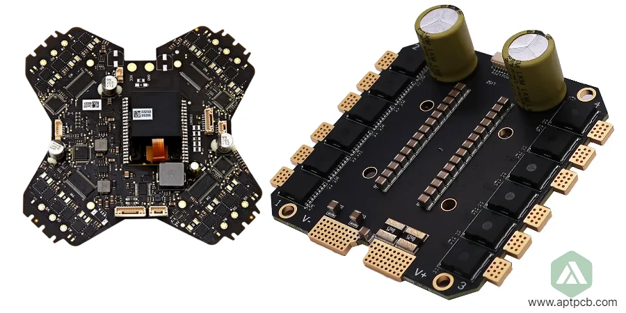
Drone and UAV PCB manufacturing for flight controllers, ESC power boards and RF modules

Drone & UAV Electronics

Drone & UAV PCB & PCBA Manufacturing

Drone and UAV PCB manufacturing turns flight-control, ESC/PDB, RF/GNSS, payload, battery and ground-control designs into build-controlled PCBAs. APTPCB supports prototype through repeat production with stackup and DFM review, controlled fabrication and assembly, and test evidence defined for each board’s mission and failure risk.

Vibration / thermal inputs
Flight Profile Review
HDI / rigid-flex options
Weight & Density
ESC / PDB current paths
Power Integrity

Get an Instant Quote

Vibration / thermal inputsFlight Profile Review
HDI / rigid-flex optionsWeight & Density
ESC / PDB current pathsPower Integrity
GNSS / telemetry / videoRF Awareness
SPI / AOI / X-rayInspection Plan
FCT / traceabilityRelease Evidence

Drone & UAV Electronics

Drone & UAV PCB Manufacturing: Lightweight Electronics Built Around Flight Risk

A drone PCBA is not just a compact electronics board; it is part of a flying system exposed to vibration, motor switching noise, battery transients, thermal cycling and RF link sensitivity. APTPCB treats each UAV board by subsystem: flight controller, ESC/PDB, telemetry, GNSS, payload, battery or ground station.

Your manufacturing package should close six build questions before release: stackup and impedance, copper and thermal paths, package and assembly risk, inspection coverage, functional-test access and traceability. APTPCB supplies the agreed PCB/PCBA evidence; the drone OEM or system integrator retains responsibility for airworthiness, regulatory approval, battery safety and final flight qualification.

Drone and UAV PCB manufacturing for flight controllers, ESC power boards and RF modules

Subsystem Controls

Which Drone PCB Subsystems Need Different Manufacturing Controls?

Use the board role to decide which manufacturing evidence matters before release.

SubsystemManufacturing control
Flight controller and autopilotlow-noise mixed-signal layouts, IMU isolation, BGA/QFN assembly evidence and sensor readout testing.
ESC and power distributioncopper weight, MOSFET thermal paths, current sensing, creepage/clearance review and high-current test planning.
RF, telemetry, video and GNSScontrolled impedance, RF launch geometry, antenna keep-out, shielding and TDR/VNA checks when specified.
Payload and gimbal electronicsconnector retention, motor-drive thermal behavior, camera/LiDAR interfaces and firmware/programming steps.
Battery, BMS and charger boardscurrent path, temperature sensing, protection circuits and charge/discharge limits defined by the customer.
Ground control and docking systemsuser-interface PCBAs, communication modules, charging stations, base stations and relay hardware.

Release Evidence

Drone PCB Release Matrix: Flight Risk to Manufacturing Evidence

SubsystemPrimary build riskRelease evidence to define
Flight controller / sensor boardVibration, IMU noise, BGA/QFN solder jointsStackup review, X-ray where needed, firmware boot and sensor readout FCT
ESC / PDB / power boardCurrent density, MOSFET heat, switching noiseCopper/thermal review, solder-volume control, load or insulation test when specified
RF / video / GNSS boardImpedance drift, antenna detuning, shield leakageImpedance coupon/TDR, RF launch review, VNA or link test if limits are supplied
Payload / gimbal boardConnector stress, motor-drive heat, interface mismatchConnector inspection, programming record, interface or motion FCT
Battery / BMS / charger boardHigh current, temperature sensing, protection responseCreepage/clearance review, charge/discharge limits, traceability and safety test per customer plan

Build Controls

Subsystem-Specific Manufacturing Controls

01

Flight Controller & Autopilot PCBs: Protect Sensor Stability

Flight controllers are especially sensitive to vibration, sensor noise and power coupling. For autopilot PCBAs, the release review covers stackup, reference planes, IMU placement, connector orientation and test access before production starts.

02

ESC, PDB & Motor-Control PCBs: Current Path, Heat and Switching Noise

ESC PCBs and power distribution boards fail differently from logic boards. The release review must consider copper weight, trace width, MOSFET package choice, thermal vias, shunt/current-sense layout, solder volume and separation from RF or sensor sections.

03

RF, Telemetry, Video & GNSS PCBs: Keep the Link Budget Manufacturable

UAV communication boards combine RF performance with tight mechanical and weight constraints. Manufacturing variation can change impedance, antenna matching and connector reliability, so the RF stackup and board finish need to be fixed early.

04

Payload, Gimbal & Mission PCBs: Reliability at the Connector Boundary

Mission electronics add cameras, LiDAR, radar, sprayers, lights, release mechanisms and gimbals to the airframe. Their build risk can concentrate at connectors, flex transitions, mounting holes and power interfaces, so those boundaries need explicit inspection and functional checks.

05

Battery, BMS & Charger PCBs: Safety Inputs Must Be Defined Up Front

Battery and charging PCBAs sit closest to the system safety boundary. APTPCB can manufacture BMS, smart battery, charger and docking PCBs to the customer specification, but pack safety, cell qualification and charger compliance are verified at product level by the OEM.

06

Ground Control, Remote & Docking PCBAs

A UAV program may also include remote controllers, base stations, repeaters, charging docks and service fixtures. These PCBAs need connector, battery, communication and user-interface controls appropriate to field use.

Inspection, Test Evidence and Release Gates for UAV PCBAs

For UAV electronics, an AOI result alone does not close every build risk. The evidence plan should connect the subsystem to the right inspection or test: SPI for paste, AOI for placement, X-ray for hidden joints, ICT or flying probe when test access exists, customer-defined FCT for function, and traceability for build history.

Typical references and acceptance language:
IPC-A-610 and J-STD-001 for electronic assembly acceptance and soldering workmanship.
IPC-A-600, IPC-6012 and IPC-2221/2222 for bare-board acceptability, performance and design rules.
ANSI/ESD S20.20 for an electronics manufacturing ESD-control program.
A customer environmental plan may reference DO-160, MIL-STD-810 or IEC 60068 test methods. These references do not make the PCB supplier the airworthiness authority; APTPCB manufactures and tests to the agreed PCB/PCBA specification.

Applications

Board Families Across Drone and UAV Platforms

Consumer Drones

Compact flight-control, camera, charging and RF PCBAs for consumer UAV platforms.

FPV / Racing Drones

Compact flight controllers, ESCs, VTX and receiver PCBAs, including common 20 × 20 mm and 30.5 × 30.5 mm mounting formats when defined in the mechanical drawing.

Industrial UAVs

Inspection, mapping and survey drones with navigation, payload and rugged power electronics.

Agricultural Drones

Spraying, monitoring and RTK-assisted UAV electronics with payload and power distribution boards.

Logistics / Delivery

Heavy-lift and docking electronics that need stronger current paths and traceable test evidence.

Defense / Security

Specialized surveillance and security UAV electronics manufactured to customer-controlled specifications.

RFQ Inputs

RFQ Checklist for Drone PCB & PCBA Projects

Fabrication package: Gerber or ODB++, drill files, stackup, board thickness, copper weight, finish, impedance targets and any rigid-flex bend requirements.
BOM and assembly data: BOM with MPN/AVL, CPL/XY file, assembly drawings, polarity notes, firmware/programming files and acceptable substitutions.
Mission profile: airframe type, vibration/shock expectations, temperature/humidity range, altitude/condensation risk and conformal-coating need.
Electrical limits: battery voltage, peak/current path, motor/ESC conditions, RF bands, antenna approach and payload interfaces.
Test and evidence: FCT procedure, fixture availability, sensor/motor/RF limits, traceability level, labeling and packaging requirements.
Responsibility boundary: identify any customer system tests, aviation/environmental standards or battery safety requirements that must be verified outside the PCB/PCBA build.

Why APTPCB

Why UAV Teams Use a Build-Controlled PCB Supplier

When APTPCB Fits the Program

APTPCB fits UAV teams that have design data and need a manufacturable stackup, controlled assembly, defined release evidence and continuity from prototype to repeat production. The same BOM rules, test assumptions and change controls can follow the board as volume grows.

What Makes This Page Different From Generic PCB Manufacturing?

Drone projects combine lightweight mechanics, power electronics, RF sensitivity and field reliability. We organize manufacturing around the flight subsystem instead of treating every board as a generic SMT job.
Subsystem-specific DFM: Flight controller, ESC, RF, payload and battery boards are reviewed against different risks instead of one generic checklist.
Evidence before volume: SPI, AOI, X-ray, ICT/flying probe and FCT are selected according to package, current, RF and sensor risk.
Prototype-to-production continuity: Early DFM notes, stackup choices and test assumptions are carried into pilot and production batches.
Clear scope boundary: APTPCB controls PCB/PCBA manufacturing evidence; the customer controls final flight qualification, regulatory approval and system-level safety.

FAQ

Drone & UAV PCB Manufacturing FAQ

What makes drone and UAV PCBs different from ordinary PCBAs?
Drone and UAV PCBAs must balance low weight, vibration tolerance, high current, RF sensitivity and thermal stress. A flight controller, ESC, GNSS module and BMS board each need different manufacturing controls and test evidence.
Which drone PCB assemblies can APTPCB manufacture?
APTPCB supports flight controller and autopilot boards, ESC and PDB boards, RF/video/GNSS modules, payload and gimbal PCBAs, BMS/charger boards, ground controllers and docking or base-station electronics.
How do you reduce vibration and EMI risk?
Manufacturing support starts with stackup, grounding, connector, coating and inspection review. We can add X-ray, impedance checks, functional tests and customer-defined environmental screening, but final vibration and flight qualification are owned by the OEM.
Can APTPCB build ESC, PDB and other high-current drone boards?
Yes, when current, voltage, copper weight, thermal interface and load-test requirements are specified. We review copper paths, MOSFET packages, thermal vias, solder volume and insulation or hi-pot needs where applicable.
Do you support RF, video and GNSS drone PCBAs?
Yes. We support controlled-impedance RF and high-speed layouts, antenna/feed-network considerations, shield-can footprints and TDR, VNA or link-level tests when the customer provides limits and fixtures.
What should we send for a drone PCB quote?
Send Gerber or ODB++ files, stackup, BOM, CPL/XY, assembly drawings, impedance and copper requirements, mission profile, firmware/programming files, FCT procedure, labeling and traceability requirements.

Global Engineering Reach

Drone PCB Manufacturing for Teams Worldwide

APTPCB supports UAV electronics teams from prototype DFM through production-intent PCB and PCBA builds.

North America
USA · Canada · Mexico

Prototype, NPI and production-intent UAV electronics builds with DFM review and customer-defined documentation.

Drone OEMNPITraceability
Europe
Germany · UK · France · Italy

Industrial, mapping, inspection and robotics programs supported with controlled fabrication and PCBA evidence packs.

Industrial UAVRFPower
Asia-Pacific
Japan · South Korea · India · Australia

Hardware teams use APTPCB for dense flight controllers, RF modules, ESC/PDB boards and payload PCBAs.

Flight ControlESCPayload
Middle East
UAE · Saudi Arabia · Israel

Security, inspection and infrastructure UAV programs supported with lot traceability and customer-defined test documentation.

SecurityInspectionDocumentation

Start a Drone & UAV PCB Manufacturing Review

Share your flight controller, ESC, RF, payload, BMS or ground-control files. We will review stackup, assembly risk, test access, evidence needs and practical lead-time options for your UAV program.