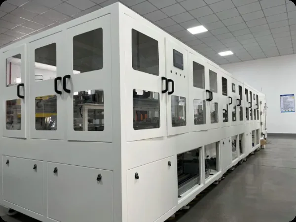
Rogers RF hybrid stack manufacturing

RF & Microwave Materials

Rogers High-Frequency PCB Manufacturing Services

APTPCB fabricates printed circuit boards from specified Rogers laminates using PTFE and ceramic-filled high-frequency processes. The exact material grade, availability, source, lot documents, and delivery schedule are confirmed for each RFQ and order.

Sub-6G -> 86 GHz
Frequency Range
Df 0.0009 - 0.004
Loss Tangent Range
24 - 48 hrs
Prototype Lead Time

Get an Instant Quote

RO4000 + FR-4Hybrid Stack-up
TDR / VNAImpedance Validation
TraceableMaterial Sourcing
Plasma DesmearPTFE Processing
+/-0.5 milTrace Tolerance
Coupon VerifiedEvery Build
4 - 40 LayersStack Complexity
ISO 9001Quality Certified
IPC-6012 CL3Acceptance Standard
RO4000 + FR-4Hybrid Stack-up
TDR / VNAImpedance Validation
TraceableMaterial Sourcing
Plasma DesmearPTFE Processing
+/-0.5 milTrace Tolerance
Coupon VerifiedEvery Build
4 - 40 LayersStack Complexity
ISO 9001Quality Certified
IPC-6012 CL3Acceptance Standard

RF materials

Rogers PCB Manufacturer for RF and Microwave Designs

QuestionAnswer
When do you need a Rogers laminate?When dielectric loss, dielectric constant stability or thickness tolerance decides whether the RF path works — typically above a few GHz, or where a matched impedance must hold across temperature.
Which families does APTPCB build?RO4000 series (RO4350B, RO4003C), RO3000 series, RT/duroid and TMM, plus hybrid stack-ups that pair Rogers cores with FR-4.
What decides the choice?Dk and its tolerance, loss tangent at your frequency, thermal coefficient and the mechanical construction — not brand name alone.

Selection Guide

How Do You Choose a Microwave Substrate by Dk, Loss and Thickness?

Below 6 GHz - RO4350B or RO4003C

For applications operating below 6 GHz - including sub-6 GHz 5G, Wi-Fi 6E/7, GPS/GNSS, and ISM-band devices - the RO4000 series is almost always the right starting point. RO4350B offers a strong balance of RF performance and manufacturing simplicity. RO4003C provides lower dielectric loss and slightly higher thermal conductivity, making it the better choice for power amplifier pallets.

6-30 GHz - RO4835 or RO3003

As operating frequency increases into the 6-30 GHz range, the transition from RO4000 to RO3000 depends on the loss budget. RO4835 extends the RO4000 family upward with improved high-temperature stability. When the loss budget is tighter, RO3003 provides much lower dielectric loss at the cost of requiring plasma desmear processing.

Above 30 GHz - RO3003, RO3035, or RT/duroid 5880

At millimeter-wave frequencies above 30 GHz - including 77 GHz automotive radar, 60 GHz WiGig, and E-band links - only PTFE-based substrates deliver acceptable insertion loss. RO3003 dominates the 77 GHz automotive radar market due to its tight Dk tolerance and temperature stability. RT/duroid 5880 remains the gold standard for the absolute lowest loss.

High-Power RF - TC350 or RO4003C

For high-power amplifier applications, thermal conductivity becomes as important as dielectric properties. TC350 extracts heat through the substrate more effectively than any other Rogers laminate. RO4003C is a more economical alternative for designs that still need strong thermal performance.

Datasheet Evaluation - RO4003C & RO4350B Specifications

When evaluating rogers-ro4003-laminate-datasheet.pdf specifications or modeling Rogers 4350B microstrips, RF hardware engineers should note the distinction between clamped stripline test data and field-solver design permittivity. IPC-TM-650 2.5.5.5 measures material Dk at 10 GHz (3.38 for RO4003C, 3.48 for RO4350B), whereas commercial EDA solvers require design Dk values (3.55 for RO4003C, 3.66 for RO4350B) across 8–40 GHz to account for dispersion and copper foil surface profile.

Selecting a Rogers laminate begins with operating frequency, insertion-loss budget, impedance model, thermal environment, copper profile, available construction, qualification requirements, and cost constraints. The guide below is a starting point; the production material is confirmed during stack-up and RFQ review.

Material Portfolio

Which High Frequency Rogers PCB Materials Fit RO4000, RO3000 and RT/duroid?

The table maps major Rogers material families to their processing and application differences. Exact grade, construction, current availability, source, lot documentation, and impedance-report scope are confirmed for the RFQ, including hybrid builds that overlap with broader PTFE PCB programs.

SeriesBase ChemistryKey CharacteristicsRepresentative Models
RO4000Hydrocarbon ceramic, woven glass reinforcementFR-4 compatible processing - no plasma desmear required. Low loss (Df 0.0027-0.004 at 10 GHz). Strong cost-performance balance for commercial RF. Widely specified for 5G sub-6 GHz infrastructure, Wi-Fi 6E/7, and GPS patch antennas.RO4350B · RO4003C · RO4835 · RO4835T · RO4450F (prepreg) · RO4360G2
RO3000PTFE with ceramic fillerExceptional Dk stability over temperature. Benchmark substrate for 77 GHz automotive radar (ADAS). Requires plasma desmear for reliable via metallization. Low moisture absorption (0.04% typ.) for stable outdoor performance.RO3003 · RO3003G2 · RO3006 · RO3010 · RO3035
RT/duroidPTFE composites (glass microfiber and ceramic filler)Lowest electrical loss available in commercial PCB laminates - Df as low as 0.0009 at 10 GHz for RT/duroid 5880. Aerospace and defense heritage. Requires plasma desmear and surface treatment for copper adhesion.RT/duroid 5880 · RT/duroid 5870 · RT/duroid 6002 · RT/duroid 6010LM
TMMThermoset microwave materials with ceramic loadingCombines the Dk stability of ceramic substrates with the processability of thermoset resin systems. Z-axis CTE closely matched to copper, providing excellent PTH reliability through extreme thermal cycling (-55 °C to +125 °C).TMM 3 · TMM 4 · TMM 6 · TMM 10 · TMM 10i
TC SeriesThermally conductive ceramic/PTFE compositesEnhanced thermal conductivity up to 1.0 W/m·K. Designed for high-power RF amplifier applications where heat extraction through the substrate is critical for maintaining long-term reliability.TC350 · TC600
AD / CLTE / CuCladVarious PTFE and ceramic compositionsLegacy and specialty substrates for heritage defense platforms, specific mechanical requirements (CTE matching), or existing qualified designs where material substitution requires formal requalification.AD250 · AD300 · CLTE-MW · CLTE-XT · CuClad 217 · CuClad 233

RO4000 Series Deep Dive

RO4350B vs RO4003C: Which Laminate Should You Use?

RO4000 hydrocarbon-ceramic laminates support commercial RF designs while using workflows closer to high-Tg FR-4 than PTFE materials. Grade selection should follow the required design Dk, loss target, thermal conditions, thickness availability, copper profile, and bonding construction; Taconic PTFE alternatives can be reviewed when the design calls for a different material system.

PropertyRO4350BRO4003CRO4835RO4835TRO4360G2Test Method
Dk @ 10 GHz3.48 ±0.053.38 ±0.053.48 ±0.053.48 ±0.056.15 ±0.15IPC-TM-650 2.5.5.5 (clamped stripline)
Df @ 10 GHz0.00370.00270.00370.00370.0038IPC-TM-650 2.5.5.5
Thermal Cond.0.62 W/m·K0.71 W/m·K0.66 W/m·K0.66 W/m·K0.80 W/m·KASTM E1461
CTE Z-axis32 ppm/°C46 ppm/°C31 ppm/°C31 ppm/°C28 ppm/°CIPC-TM-650 2.4.41
Tg (DSC)>280 °C>280 °C>280 °C>280 °C>280 °CIPC-TM-650 2.4.25
Plasma RequiredNoNoNoNoNo—
Available Thicknesses6.6 / 10 / 20 / 30 / 60 mil8 / 10 / 20 / 32 / 60 mil6.6 / 10 / 20 / 30 / 60 mil6.6 / 10 / 20 / 30 / 60 mil10 / 20 / 25 / 30 mil—

Data sourced from Rogers Corporation published datasheets. Design Dk values for impedance modeling may differ from 10 GHz clamped stripline values - consult our CAM team for Polar Si9000 simulation-ready data.

PTFE Series Deep Dive

When Should You Use RO3000 or RT/duroid?

PTFE-based RO3000 and RT/duroid grades provide lower-loss options for selected microwave and millimeter-wave designs. Their drilling, hole-wall preparation, bonding, dimensional behavior, and copper treatment must be reviewed by grade rather than treated as a standard FR-4 process.

PropertyRO3003RO3006RO3010RT/duroid 5880RT/duroid 6002RT/duroid 6006
Dk @ 10 GHz3.00 ±0.046.15 ±0.1510.2 ±0.302.20 ±0.022.94 ±0.046.15 ±0.15
Df @ 10 GHz0.00100.00200.00230.00090.00120.0019
Thermal Cond.0.50 W/m·K0.79 W/m·K0.95 W/m·K0.20 W/m·K0.60 W/m·K0.48 W/m·K
CTE Z-axis24 ppm/°C17 ppm/°C17 ppm/°C237 ppm/°C24 ppm/°C24 ppm/°C
Dk vs Temp StabilityExcellentExcellentGoodGoodExcellentGood
Plasma DesmearYesYesYesYesYesYes
Common Thicknesses5 / 10 / 20 / 25 / 50 mil10 / 25 / 50 mil10 / 25 / 50 mil5 / 10 / 15 / 20 / 31 / 62 mil10 / 20 / 30 / 60 mil25 / 50 / 75 mil
Primary Applications77 GHz radar, mmWave 5GCompact filters, antennasDielectric resonatorsSatellite LNA, military EWAerospace radar, striplineDRO, high-Dk microstrip

PTFE substrates have no meaningful glass transition temperature (Tg). Z-axis CTE values for RT/duroid 5880 are significantly higher than ceramic-filled PTFE - this must be accounted for in multilayer stack-up design.

Hybrid Stack-Up Engineering

Can You Mix Rogers and FR-4 in One Stack-Up?

A fully Rogers multilayer board - where every core and prepreg layer uses Rogers material - can be prohibitively expensive. For a 10-layer design, the laminate cost alone can run five to ten times higher than an equivalent FR-4 construction. Hybrid stack-ups offer a practical alternative that dramatically reduces this cost gap while preserving RF performance for global mass production.

In a hybrid construction, the RF-critical signal layers use Rogers cores (RO4350B, RO3003, or RT/duroid), while structural, power-distribution, and ground layers are built on conventional High-Tg FR-4. The two material systems are bonded together using a compatible low-loss prepreg - typically RO4450F for RO4000 signal layers, or specialized bondplys like Rogers 2929 for PTFE-to-FR-4 bonds. This is exactly the kind of mixed-dielectric planning covered in a formal PCB stack-up engineering review.

Our CAM engineers model every hybrid cross-section to verify impedance continuity at the dielectric transitions. We select the correct bonding prepreg, model the lamination press cycle, and validate the final stack-up dimensions against Polar Si9000 impedance simulation before committing material to production. The result is a board that meets your insertion-loss budget at a total cost 30-50% lower than an all-Rogers construction.

Plasma desmear chamber for PTFE Rogers laminates

Reference Stackups

What Stack-Up Details Must Be Confirmed Before RFQ?

These representative constructions illustrate Rogers and hybrid stack-up options. The production stack-up, press profile, impedance model, material source, and availability are released only after review of the actual Gerber or ODB++, frequency, copper, thickness, and tolerance requirements.

ConfigurationLayer CountSignal LayersStructural LayersBonding SystemTarget Applications
Pure RO40002-6 layersRO4350B or RO4003C—RO4450F prepreg5G antenna feeds, GPS patches, Wi-Fi front-end modules
RO4000 Hybrid4-12 layersRO4350B / RO4003CFR-4 or FR408HRRO4450F + FR-4 prepreg5G base stations, radar T/R modules with digital control
RO3000 Pure2-4 layersRO3003 / RO3006—RO3003 bondply77 GHz automotive radar, mmWave sensor arrays
RO3000 Hybrid4-8 layersRO3003 (signal)FR-4 or Megtron 6Rogers 2929ADAS radar with digital processing layers
RT/duroid Pure2-4 layersRT/duroid 5880—RT/duroid bondplySatellite LNA, military EW receivers, space-rated boards
RT/duroid Hybrid4-10 layersRT/duroid 5880 / 6002FR-4 or polyimide2929 bondply + FR-4 prepregPhased-array antenna panels, defense radar with power distribution
Multi-Rogers Mixed6-12 layersRO4350B (outer) + RO3003 (inner)FR-4RO4450FMulti-band antenna systems, broadband EW boards

Manufacturing Expertise

How Is Rogers PCB Fabrication Controlled Without Damaging Dk?

Processing PTFE and ceramic-loaded laminates demands specialized equipment and chemistry that goes well beyond standard FR-4 workflows, which is why these builds follow a dedicated expedited RF fabrication process rather than a commodity FR-4 line.

01

PTFE Plasma Desmear & Surface Activation

RO3000 and RT/duroid substrates are chemically inert - standard alkaline permanganate desmear chemistry cannot etch PTFE. Our factory operates dedicated plasma treatment chambers using controlled CF4/O2 gas mixtures to activate the hole wall surface before electroless copper deposition.

02

Controlled Impedance Etching & TDR Validation

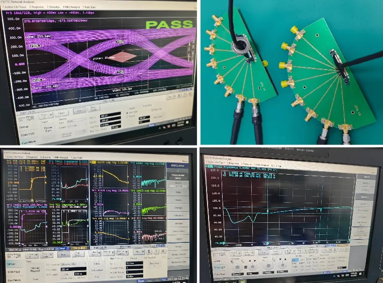
Precision etching on Rogers substrates holds trace-width tolerance within ±0.5 mil (12.7 μm), critical for maintaining 50 Ω single-ended or 100 Ω differential targets with less than ±7% total tolerance. Every production panel includes TDR-measured impedance coupons, probed on calibrated time-domain reflectometry equipment to record the measured values against your pre-production simulation target.

03

RF-Optimized Surface Finishes

For Rogers builds, we recommend immersion silver for the lowest surface resistivity on high-frequency signal traces. ENIG is recommended for assemblies carrying fine-pitch MMIC packages requiring multi-reflow capability. ENEPIG is available for antenna-grade boards requiring PIM screening.

04

Humidity-Controlled Storage & Bake Protocols

PTFE-based Rogers laminates absorb atmospheric moisture over time. All incoming Rogers material is stored in our climate-controlled warehouse and each lot undergoes a documented pre-lamination bake cycle per Rogers' published recommendations.

05

Lamination Press Profile Engineering

Different Rogers materials require different press profiles. RO4000 series laminates cure at thermoset temperatures similar to FR-4, but PTFE-based materials bond at different temperatures with specific ramp rates. Our press programs are validated with thermocouple-monitored test runs.

06

Modified Drill Programs for PTFE

PTFE is a soft thermoplastic material - standard drill programs designed for rigid FR-4 generate excessive heat that smears fluoropolymer across the hole wall. Our PTFE drill programs use reduced spindle speeds, optimized feed rates, and specialized entry and exit materials.

Quality & Validation

What RF Validation Evidence Should You Request?

Rogers-based RF and microwave boards require the manufactured stack-up, conductor geometry, material lot, surface finish, and impedance evidence to remain tied to the released design. The acceptance target and document package therefore need to be defined before fabrication rather than inferred from a laminate family alone.

When specified in the order, the release package can include material certificate and lot traceability, approved stack-up, AOI and electrical-test records, and TDR coupon results compared with the customer-defined target and tolerance.

For programs requiring deeper characterization, available options include VNA S-parameter measurements on dedicated test vehicles up to 40 GHz, cross-section micrographs with dimensional annotations, IST reliability testing, IPC-6012 Class 3 documentation, and serialized board traceability. These are quoted and released according to the actual test vehicle, acceptance method, sampling plan, and customer documentation requirement.

TDR validation on Rogers PCB impedance coupon

Industry Applications

Which Applications Need Rogers Instead of FR-4?

Rogers substrates are specified across the most demanding RF, microwave, and millimeter-wave applications in telecommunications, automotive, aerospace, and defense industries, especially for antenna PCB and front-end signal-chain hardware.

Telecommunications

5G & Wireless Infrastructure

Massive MIMO antenna arrays and beamforming networks for sub-6 GHz and mmWave 5G base stations. RO4350B and RO4835 are the workhorses for sub-6 GHz antenna panels. For mmWave bands, RO3003 and hybrid RO3003/FR-4 stack-ups provide the low loss needed for patch array feed networks operating at 28 GHz and above.

Automotive

77 GHz ADAS Radar

Short-range and long-range automotive radar sensors for adaptive cruise control and blind-spot detection. RO3003 has become the de facto standard substrate for 77 GHz radar antenna arrays, and its exceptional Dk-versus-temperature stability meets stringent automotive qualification requirements.

Aerospace & Defense

Phased-Array Radar & EW

AESA radar transmit/receive modules, electronic warfare wideband receivers, and satellite communication transponders. RT/duroid 5880 remains the gold-standard substrate for military-grade low-noise amplifiers and stripline feed networks, with a heritage spanning MIL-qualified platforms across NATO deployments.

Medical

RF Medical Devices

MRI surface coils, RF ablation generators for cardiac treatment, and wireless implant telemetry systems. These applications require substrates with stable permittivity under varying biological loading conditions, making Rogers ceramic-filled laminates the preferred choice over raw PTFE for surgical-proximity electronics.

Satellite & SATCOM

LEO Terminals & Earth Stations

Low-earth-orbit (LEO) constellation user terminals, high-throughput VSAT modems, and Ka-band earth station feed assemblies. Hybrid Rogers/FR-4 stack-ups isolate the noise-critical receive-chain LNA on ultra-low-loss RT/duroid 5880 or RO3003 substrates to preserve system noise figure.

Test & Instrumentation

Precision Measurement Equipment

Vector network analyzer (VNA) calibration substrates, reference transmission lines, and probe-station interposers. When measurement uncertainty must be minimized, the tightly controlled, and time-stable dielectric properties of Rogers laminates provide a trusted metrology baseline from DC through W-band (110 GHz).

Frequently Asked Questions

Rogers PCB: Questions Before RFQ

How is Rogers material availability confirmed for a quick production start?
Specify the exact Rogers grade, core or prepreg thickness, copper profile, and required documents in the RFQ. We will confirm current availability, source, lot documentation, and lead time for that combination; permanent stock and a fixed procurement route are not assumed. Programs that also evaluate Arlon microwave laminates can be reviewed in the same material plan.
How does the total cost of a Rogers PCB compare to standard FR-4?
For the RO4000 series, raw laminate cost runs roughly three to five times the price of commodity FR-4 PCB materials. PTFE-based materials (RO3003, RT/duroid) can be eight to twelve times the FR-4 price, and they also incur additional processing costs for plasma desmear. However, hybrid constructions that pair one or two Rogers signal layers with FR-4 structural layers can reduce material expense by 30-50% compared to an all-Rogers build while preserving RF performance.
Can you manufacture multilayer Rogers PCBs with more than two layers?
Yes. We routinely produce four- to twelve-layer boards using RO4000-series cores bonded with RO4450F prepreg, multilayer RO3000 panels for automotive radar, and high-layer-count hybrid constructions combining Rogers signal layers with FR-4 for demanding microwave PCB programs. Our CAM engineers model the lamination press cycle and generate impedance simulation data before any material is committed to production.
What surface finishes do you recommend for Rogers RF boards?
For high-frequency RF signal traces, Immersion Silver (5-15 μin) is our top recommendation as it provides the lowest surface resistivity, minimizing skin-effect conductor loss. ENIG is highly reliable for assemblies with fine-pitch SMT components. ENEPIG is recommended if Passive Intermodulation is a concern. We strongly advise against using HASL for RF applications due to its highly uneven surface topography.
What is the difference between RO4350B and RO4003C?
Both are hydrocarbon ceramic laminates that process with standard FR-4 chemistry. RO4003C has approximately 27% lower dielectric loss and 15% higher thermal conductivity, but it is a non-cross-linked hydrocarbon that cannot be used as a prepreg. RO4350B is cross-linked and pairs directly with RO4450F prepreg for straightforward multilayer lamination.
Do you offer turnkey assembly (PCBA) services for Rogers PCBs?
Yes. We provide full turnkey PCB assembly for Rogers-based boards including component sourcing, solder paste printing, SMT placement, reflow soldering, AOI, X-ray inspection for BGAs, and functional testing. Our assembly team adjusts reflow thermal profiles specifically for Rogers substrates to prevent delamination during the solder reflow cycle.
What is the typical lead time for Rogers PCB prototypes?
After the exact grade, thickness, and current availability are confirmed during RFQ review, simple two-layer prototypes may be evaluated at 3-5 working days and multilayer or hybrid constructions at 7-10 working days. PTFE builds require additional plasma-desmear time; any expedited schedule is committed only after material and DFM review.

RFQ and Release Package

What Should You Submit for a Rogers PCB Quote?

Design and Material Inputs

Provide Gerber or ODB++ data, the proposed stack-up, exact Rogers grade and dielectric thickness, copper weight and profile, operating frequency or channel requirement, controlled-impedance targets and tolerances, surface finish, quantity, and expected production volume.

Acceptance and Documentation Inputs

Identify the required material CoC and lot traceability, electrical-test method, impedance-coupon construction, TDR target and tolerance, sampling plan, and any VNA, microsection, IST, or Class 3 documentation needed for release.

Order-Confirmed Deliverables

The quoted package can include an approved production stack-up, material CoC and lot records, electrical-test and inspection records, and impedance-coupon TDR data. VNA results, annotated microsections, IST results, and additional qualification records are supplied only when the test vehicle, method, acceptance criteria, and reporting scope are included in the order.

A Rogers PCB quotation becomes production-ready only after the material construction, RF targets, acceptance limits, and required records are defined. Availability, source, lot documents, test scope, and delivery are then confirmed for the quoted build and order.

Interactive Tool

Rogers Material Quick Selector

Select a Rogers material model to view its key specifications. Data sourced from Rogers Corporation published datasheets.

Choose a Rogers Model
Select a model above to view its specifications, available thicknesses, and recommended applications.

Global Engineering Reach

Rogers PCB Manufacturing for Engineers Worldwide

Engineering teams across defense, automotive, and telecoms on four continents rely on APTPCB for Rogers PCB fabrication. Our English-language DFM review, online quoting, and Gerber upload workflow make international collaboration straightforward.

North America
USA · Canada · Mexico

Defense contractors (RT/duroid 5880, RO3003), 5G infrastructure suppliers (RO4350B massive MIMO), and Silicon Valley RF startups use APTPCB for Rogers prototypes and NPI runs. ITAR-aware documentation available.

Defense5GITAR-Aware
Europe
Germany · UK · Sweden · France

Automotive radar (77 GHz RO3003) teams in Germany and tier-1 ADAS suppliers, UK/French defense EW programs (RT/duroid), and Nordic telecom R&D labs sourcing Rogers prototypes with competitive lead times.

ADAS RadarEW SystemsTelecom
Asia-Pacific
Japan · South Korea · Taiwan · India

5G base station antenna panel manufacturers, satellite terminal developers, and hardware startups across APAC leverage our online platform for RO4350B and RO3003 builds with 24-hour DFM feedback.

5G InfraSatelliteNPI
Israel & Middle East
Israel · UAE · Saudi Arabia

Aerospace and defense programs, surveillance radar builds (RT/duroid, TMM), and SATCOM projects. We support full qualification documentation packages aligned to defense procurement requirements in the region.

AerospaceDefense RadarSATCOM

Ready to Lock Your Rogers RF Stack-Up?

Share your Gerber or ODB++ data, proposed stack-up, exact Rogers grade and thickness, copper profile, operating frequency, impedance targets, surface finish, quantity, and required documentation. Our engineering team will review the construction and confirm the quoted material, validation package, and delivery schedule.