PCB quality laboratory used for inspection, electrical testing, and release review

Inspection tied to release evidence

PCB Quality Assurance from Data Review to Shipment Release

PCB quality assurance is the documented process of translating fabrication requirements into inspection points, acceptance evidence, and shipment-release decisions. This page connects common PCB risks with AOI, electrical test, impedance coupons, microsections, dimensional checks, and the records buyers should define before quotation.

Gerber or ODB++
Released fabrication data
E-test + AOI
Connectivity and image checks
Release records
Evidence matched to the order

Get an Instant Quote

AOIInner-layer image comparison
Electrical testContinuity and isolation
TDRImpedance verification when specified
MicrosectionCross-section evidence when required
X-ray alignmentAlignment evidence when required
XRFFinish-thickness measurement when specified
4–32 layersVerified fabrication range
Lot traceabilityMaterial and process record linkage
AOIInner-layer image comparison
Electrical testContinuity and isolation
TDRImpedance verification when specified
MicrosectionCross-section evidence when required
X-ray alignmentAlignment evidence when required
XRFFinish-thickness measurement when specified
4–32 layersVerified fabrication range
Lot traceabilityMaterial and process record linkage

Three inspection layers

Where PCB defects are intercepted before shipment

End-of-line testing cannot replace process controls. A useful quality plan places checks where the defect can still be contained and links each result to a release decision.

Before lamination

Image and inner-layer verification

Released artwork is reviewed before imaging, and AOI can compare etched inner-layer features with the approved data before the layers are laminated. This stage targets opens, shorts, residual copper, and feature deviations that become inaccessible later.

During structure build

Registration, drilling, and plating evidence

Registration controls, drill review, plating records, and microsection sampling are selected according to stack-up complexity and the agreed acceptance plan. The objective is to detect structural risk before final surface finish and shipment.

Before release

Electrical, dimensional, and document review

Final release checks the netlist-based electrical result, required dimensions, finish and marking condition, requested reports, and lot identity against the current drawing and purchase requirements.

Electrical test planning

Continuity and isolation checks need a released netlist

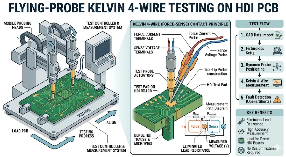
Electrical testing is most useful when it is tied to the released connectivity data. A netlist-based test checks for unintended opens and shorts; the method may use flying probe for flexible setup or a dedicated fixture when the order and repeat volume justify tooling.

Kelvin four-wire measurement can be specified when low-resistance structures require separation of lead resistance from the measurement. High-voltage or other special electrical tests are not assumed: voltage, dwell time, limits, test points, and reporting must be defined by the customer's approved requirement.

Electrical results should be reviewed together with drilling and plated-hole controls and controlled-impedance requirements, because a passing continuity test alone does not describe every structural or signal-integrity risk.

Flying-probe electrical test for PCB continuity and isolation verification

Decision matrix

PCB quality control matrix: risk, method, evidence, release decision

Use this matrix to define which evidence belongs in the quotation and which result must be reviewed before the lot is released.

Fabrication riskControl or inspectionTypical evidenceRelease question
Wrong data or revisionCAM and fabrication-drawing reviewApproved data set and engineering query closureAre all files and exceptions tied to one released revision?
Inner-layer open or shortAOI before laminationInspection result and contained nonconformance recordDid the layer meet the approved image data?
Registration or plated-hole riskRegistration control and microsection when specifiedCross-section image or report linked to the lotDo inspected features meet the stated acceptance criteria?
Continuity or isolation faultNetlist-based electrical testElectrical-test result for the released connectivity dataDid the tested board pass the approved limits?
Impedance outside targetTDR coupon test when controlled impedance is specifiedTarget, tolerance, coupon structure, and measured resultDoes the coupon result fall inside the released tolerance?
Finish or solder-mask issueVisual inspection and specified thickness or adhesion checkFinish, mask, and marking inspection recordDoes the surface condition match the fabrication specification?
Incomplete shipment evidenceFinal document and lot-identity reviewCertificate, requested reports, quantity, and lot referenceIs every required record present before shipment release?

Reference framework: IPC-A-600 for printed-board acceptability, IPC-6012F for rigid printed-board qualification and performance, IPC-9252B for electrical testing of unpopulated printed boards, and applicable IPC-TM-650 test methods. The purchase drawing and agreed customer specification remain the release authority.

Evidence levels

Choose release documentation according to product risk

Not every order needs the same inspection package. Defining the evidence level before quotation avoids both missing records and unnecessary test cost.

Standard commercial build

Core fabrication release

Define the drawing revision, material and finish, acceptance class, electrical test requirement, marking, quantity, and certificate needs. Add dimensional reporting only where dimensions are release-critical.

Controlled-impedance build

Stack-up and coupon evidence

Release the target impedance, tolerance, trace geometry, reference structure, and coupon expectation. The quotation should identify whether a TDR report or coupon data is required with shipment.

High-reliability or regulated product

Customer-defined acceptance package

Specify class, sampling, microsection locations, special tests, record retention, traceability, and change-notification expectations. Final product or system compliance remains the customer's responsibility.

Release package checklist

Six gates for a reviewable PCB quality release

A release package is useful only when each result can be traced to the current data set, the stated acceptance rule, and the affected production lot.

1. Data and revision gate

Confirm Gerber or ODB++, drill data, netlist when available, stack-up, fabrication drawing, panel requirements, and revision status. Resolve contradictory dimensions or notes before tooling is released.

2. Material and process gate

Confirm laminate family, copper weight, surface finish, solder mask, marking, controlled-depth features, filled vias, and any customer-approved substitutions or restrictions.

3. In-process inspection gate

Link AOI, registration, drill, plating, and other selected in-process results to the lot. A failed result remains contained until documented disposition is approved.

4. Electrical and impedance gate

Verify the electrical test used the released connectivity data. For controlled impedance, confirm the target, tolerance, coupon construction, and required report before accepting the result.

5. Final inspection and records gate

Review dimensions identified as critical, board outline, finish and mask condition, legend, marking, quantity, packaging, certificate, and every report required by the purchase order.

6. RFQ input checklist

Provide fabrication data, drill files, netlist, stack-up, drawing, IPC class or customer specification, impedance table, critical dimensions, special tests, sampling rules, traceability needs, and the exact shipment records required.


Buyer and engineering FAQ

PCB quality assurance questions before quotation

What should a PCB quality plan define before production?
It should define the applicable drawing revision, IPC class or customer specification, critical dimensions, impedance targets, electrical test requirements, coupon or microsection needs, marking rules, and the records required with shipment.
How does inner-layer AOI support multilayer PCB quality?
Inner-layer AOI compares etched copper features with the released image data before lamination. It helps detect opens, shorts, residual copper, and feature deviations while the affected layer can still be contained.
What does final PCB electrical testing verify?
A netlist-based electrical test checks continuity and isolation against the released connectivity data. IPC-9252B provides the requirements framework for electrical testing of unpopulated printed boards; flying-probe or fixture methods may be selected according to board design, quantity, and the approved test strategy.
When is TDR impedance testing required?
TDR testing is appropriate when the fabrication package specifies controlled-impedance structures and an acceptance tolerance. The stack-up, target impedance, trace geometry, reference planes, and coupon requirements should be released before production.
What can a PCB microsection show?
A prepared cross-section can support evaluation of plated-hole structure, internal connections, dielectric condition, and other features specified by the applicable inspection plan. Sampling location and acceptance criteria must be agreed in advance.
Are IPC Class 2 and Class 3 requirements interchangeable?
No. The selected performance class affects acceptance criteria and inspection planning. The class and any customer-specific exceptions should be stated on the drawing or purchase documentation rather than assumed after fabrication begins.
How is surface-finish quality checked?
The inspection plan can include visual condition, solderability-related checks, and thickness measurement where the finish specification requires it. The finish type, thickness limits, test method, and reporting need to be part of the released requirements.
What quality records can be requested with a PCB shipment?
Depending on the order, the release package may include certificate of conformance, electrical-test result, impedance report, microsection image or report, dimensional results, material or finish records, and lot identification.
How are nonconforming PCB results handled?
The affected material should be identified and held while the result is reviewed against the approved acceptance criteria. Disposition, rework, rebuild, or concession requires documented authorization appropriate to the order.
What files help APTPCB quote the correct inspection scope?
Send Gerber or ODB++, drill data, stack-up, fabrication drawing, netlist when available, impedance table, finish and material requirements, acceptance class, critical dimensions, special tests, and the release documents you expect.

Remote evidence review

A quality package that distributed teams can evaluate

The same release logic supports buyers and engineering teams in different regions: requirements first, evidence linked to the lot, and documented disposition of exceptions.

North America
Drawing and report alignment

State the governing drawing, acceptance class, special tests, and shipment records so procurement and engineering review the same release basis.

DrawingReportsTraceability
Europe
Material and compliance inputs

Include material restrictions, declarations needed for the order, finish requirements, traceability, and the party responsible for final product compliance.

MaterialsDeclarationsRecords
Asia-Pacific
Production-data continuity

Keep tooling, panel, test, and inspection outputs tied to one released data set when production quantities or repeat orders change.

Data setPanelRepeat order
Middle East
High-reliability review scope

Define microsection, impedance, dimensional, environmental, or other special evidence before quotation; do not infer final system qualification from PCB inspection alone.

AcceptanceSpecial testsScope

Define the PCB inspection package before production

Upload fabrication data, stack-up, drawing, netlist, impedance table, acceptance criteria, and required shipment records. Engineering will review the test and evidence scope for quotation.