IPC 6013 CLASS 3

Rigid-Flex PCB Manufacturing — Precise, Reliable, Production Ready

Stack rigid FR-4 or low-loss cores with adhesiveless polyimide flex tails, 3/3 mil LDI imaging, and 0.10 mm laser microvias to deliver compact electronics that fold, hinge, and survive 100k flex cycles.

  • Adhesiveless PI flex cores
  • 3/3 mil LDI imaging
  • 0.10 mm laser microvias
  • Laser-defined coverlay
  • Copper button plating
  • 100k flex-cycle validation

Get an Instant Quote

Full Quote →

Rigid-Flex Engineering, Fabrication, and Cleanroom Assembly

APTPCB engineers read IPC-2581 or ODB++ data, validate stackups, and align neutral axes so rigid and flex sections share copper, prepreg, and drill limits.

Coverlay apertures, button plating, selective stiffeners, and PSA windows are modeled before release to ensure connectors sit flat while flex tails remain compliant.

We maintain a single workflow from lamination to cleanroom SMT carriers, so 01005 assemblies, press-fit connectors, and bend testing happen under one engineering change process.

APTPCB's rigid-flex design guide shows how replacing connectors and harnesses with 3D folding can trim up to 50% of stack height while boosting reliability. We deploy that approach in wearables, flight-deck modules, and medical imaging by pre-forming flex limbs and co-curing them with rigid sections.

The same guide details material prep, lamination windows, selective bonding, drilling/plating, and finishing tolerances. We borrow those parameters for copper cleaning, bondply control, coverlay/stiffener alignment, and ENIG/HASL finishing so rigid/flex interfaces stay consistent.

Rigid-Flex Engineering, Fabrication, and Cleanroom Assembly

Programs Delivered with Rigid-Flex

Representative builds spanning aerospace harness replacements, medical implants, automotive interiors, and camera or sensing modules.

Cockpit & cabin harness

Cockpit & cabin harness

Imaging & lidar modules

Imaging & lidar modules

Wearable compute cores

Wearable compute cores

EV HMI controllers

EV HMI controllers

Satellite avionics

Satellite avionics

Medical probes & catheters

Medical probes & catheters

Rigid-Flex Reliability Backed by IPC 6013

Sequential lamination, laser coverlay, and controlled bend validation keep rigid and flex sections aligned through thermal shock and dynamic cycling.

Download Capabilities
Rigid 4–10 layersFlex 2–6 layersButton-plated viasLaser coverlay relief±5% impedance flex/rigid100k flex-cycle logs

APTPCB Rigid-Flex Manufacturing Services

From concept stackup to qualified production, we engineer rigid-flex boards that fold, hinge, and survive repeated stress without sacrificing impedance or assembly throughput.

Rigid-Flex Architectures

Choose the right rigid/flex split, layer count, and stiffener mix to balance density, bend profile, and cost.

  • Type 1 Rigid-Flex – Single flex core laminated to two rigid sections for static folds and connector savings.
  • Type 2 Rigid-Flex – Multiple flex layers with microvias between rigid and flex for higher routing density.
  • Air-gap Rigid-Flex – Independent flex tongues between rigid islands to improve dynamic reliability.
  • Bookbinder Rigid-Flex – Offset flex layers of different lengths prevent stress at the fold in high-layer builds.
  • Any-Layer Rigid-Flex – Flex and rigid sections share stacked microvias for ultra-compact camera or sensor modules.

Interconnect & Bend Features

  • Staggered Microvias: Layer-to-layer interconnects that avoid stacking over bend areas for better fatigue life.
  • Button Plated PTH: Copper buttons reinforce vias crossing rigid-to-flex transitions.
  • Back-drilled Interconnect: Removes stubs in rigid sections feeding flex tails for SerDes and RF signals.
  • Selective Stiffener Vias: Dedicated vias tie ground pours to copper stiffeners for EMI control.
  • Laser Skived Coverlay: Precisely opens pads and relieves adhesive around dynamic bends.
  • Embedded Copper Coins: Local thermal paths in rigid sections without adding mass to flex regions.

Stackup Examples

  • 8 Layer (2 Flex + 6 Rigid): Two 25 µm PI layers sandwiched between FR-4 cores for wearable compute.
  • 12 Layer Bookbinder: Alternating flex tongues with offset lengths to protect 0.4 mm pitch BGAs.
  • Rigid-Flex-Rigid (6R-4F-6R): High-density avionics module with low-loss rigid materials and RA copper flex tails.

Materials & Design Guidelines

Adhesiveless PI, LCP, and matched FR-4 or low-loss rigid materials keep coefficients aligned. Copper button plating, hatched grounds, and coverlay relief manage impedance without cracking.

  • Match CTE between rigid and flex sections to avoid warpage during lamination.
  • Use RA copper ≤ 35 µm in dynamic bends; reserve thicker copper for static sections.
  • Keep plated through-holes out of bend areas and maintain 10× thickness bend radius minimum.
  • Design coverlay relief with teardrops and fillets to prevent cracking at pad edges.

Reliability & Validation

Every build includes electrical test, AOI, X-ray of buried vias, and optional 100k-cycle bend testing with resistance logging to certify mechanical integrity.

Cost & Application Guidance

  • Type 1 Rigid-Flex: Lowest cost when only one dynamic flex tail replaces wiring.
  • Bookbinder / multilayer: Budget for additional lamination passes but consolidate rigid islands to reduce tooling.
  • High-speed rigid-flex: Use low-loss rigid cores only where required to control material spend.

Rigid-Flex Manufacturing Flow

1

Stackup & DFx Workshop

Validate rigid/flex splits, impedance targets, and neutral axis placement before tooling.

2

Imaging & Microvia Drilling

LDI imaging and UV/CO₂ drilling define 3/3 mil traces and 0.10 mm blind vias.

3

Sequential Lamination

Bond flex cores to rigid sections with controlled temperature, pressure, and registration.

4

Coverlay & Stiffener Lamination

Laser-cut coverlay, add FR-4/PI/stainless stiffeners, and cure PSA or epoxy.

5

Routing & Bend Prep

Skive step-downs, radius edges, and perform depanel to fixture-ready coupons.

6

Assembly & Validation

Cleanroom SMT carriers, press-fit assembly, and dynamic bend tests close the loop.

7

Material Prep & Incoming QA

We panelize copper-clad PI and FR-4 per traveler, then inspect copper cleanliness and thickness to satisfy IPC-6013 flex criteria.

8

Selective Stack-Up & Cure

After inner layers are imaged, layers are aligned and laminated through multiple press cycles while bond-inhibit regions keep flex areas free.

9

Drilling, Plating & Final Finish

Laser/mechanical drilling, copper plating, outer-layer imaging, coverlay/stiffeners, and ENIG/HASL finishing precede 100% electrical and visual inspection.

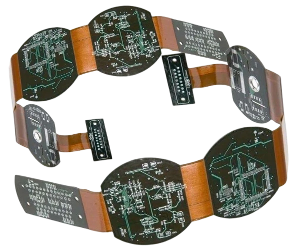
Rigid-Flex CAM & Stackup Engineering

CAM teams merge Gerber/Odb data with bend specs, define coverlay patterns, button plating, and impedance coupons, and align stackups with factory capabilities.

  • Review IPC-2223 design constraints, bend radii, and keep-out zones.
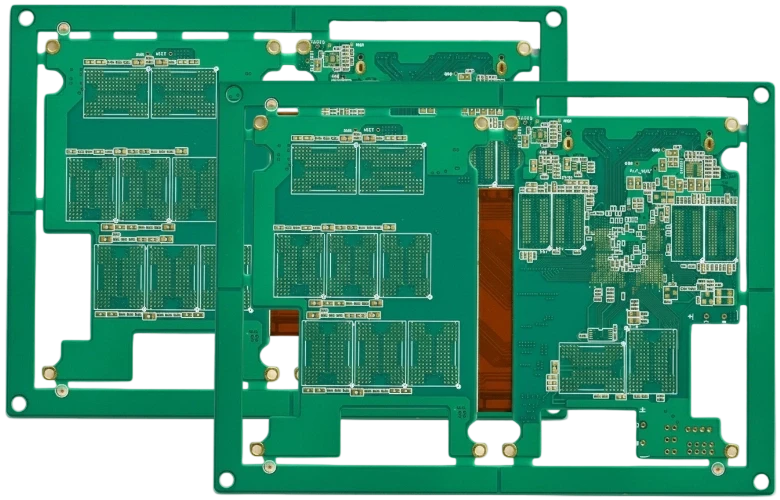
  • Align rigid/flex stackups with available copper weights and dielectric thicknesses.
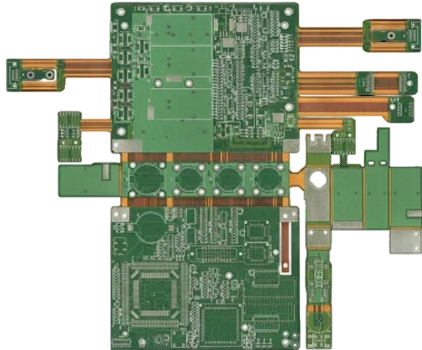
  • Define coverlay openings, teardrops, and hatched grounds for impedance stability.
  • Specify button plating, staggered microvias, and back-drill locations.
  • Plan stiffener outlines, PSA windows, and carrier tooling holes.
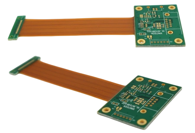
  • Document impedance coupons plus dynamic flex coupons per lot.
  • Release fabrication notes covering bake/lamination cycles and packaging.

Manufacturing Execution & SPC Feedback

Process engineers monitor lamination pressure, drill alignment, and bend sampling, feeding SPC data back to CAM for continual refinement.

  • Track lamination pressure/temperature to avoid resin squeeze-out into flex zones.
  • Verify LDI alignment and microvia quality with inline AOI.
  • Inspect coverlay adhesion and relief geometry after laser processing.
  • Check stiffener planarity and PSA cure before routing.
  • Run bend/torsion tests on sample coupons with logged resistance.
  • Complete AOI, flying probe, and X-ray on rigid sections and via transitions.
  • Package finished boards with carriers, humidity indicators, and bend instructions.
3/3 mil

Line / Space

LDI imaging across rigid + flex

0.10 mm

Laser Via

Blind / buried microvias

100k+

Flex Cycles

Dynamic hinge validation

±5%

Impedance

Rigid + flex tolerance

Advantages of Rigid-Flex PCBs

Blend rigid stability with flexible routing to shrink products and raise reliability.

3D Packaging Freedom

Route signals through folds and hinges to fit electronics in non-planar enclosures.

Higher Reliability

Eliminate fragile connectors and cables; rigid-flex survives shock, vibration, and movement.

Better Signal Integrity

Shorter interconnects and tightly controlled impedance improve RF and high-speed margins.

Lower System Weight

Integrated flex tails replace harnesses, reducing grams across wearable and aerospace platforms.

Assembly Efficiency

Rigid-flex builds arrive with carriers and stiffeners, accelerating SMT, test, and final integration.

Documented Validation

Bend logs, X-ray, and IPC 6013 Class 3 inspection trail every lot for regulated industries.

Mission-Critical Durability

Fewer connectors and flexible sections absorb vibration, shock, and thermal cycling — ideal for aerospace, defense, and medical wearables.

Streamlined Testing & QA

Integrated interconnects reduce part count, simplify fixture coverage, and cut assembly errors, so validation is faster and more thorough.

Why Choose APTPCB?

Rigid-flex replaces connectors and harnesses, enabling lighter assemblies, faster build, and better signal integrity in 3D packaging.

WearablesAerospaceMedicalCamerasEV interiorsRobotics
APTPCB production line
Rigid-flex lamination line

Rigid-Flex PCB Applications

Use rigid-flex when space, reliability, or mechanical freedom demand a hybrid interconnect.

From cockpits to surgical tools to foldable consumer devices, rigid-flex reduces part count while improving durability.

Aerospace & Defense

Lightweight harness replacements for avionics, satellites, and mission systems.

CockpitUAVSatellitesRadarMissile

Medical & Life Sciences

Sterilizable flex sections and rigid implant controllers in one build.

CathetersImagingWearablesDiagnosticsSurgical

Automotive & EV Interiors

HMI clusters, HUDs, and battery monitoring modules cut connectors and wiring.

HUDHMIADASBatteryLighting

Consumer & Wearables

Foldable devices and premium wearables rely on rigid-flex tails for ultra-thin packaging.

FoldablesHeadsetsSmartwatchesCamerasAudio

Computing & Imaging

Camera modules and compute cards integrate rigid cores with flex jumpers for signal integrity.

CamerasSensorsModulesStorageEdge AI

Industrial & Robotics

Robots, inspection tools, and instrumentation need moving interconnects that do not fail.

RoboticsFactoryInspectionInstrumentationIoT

Telecom & RF

Low-loss rigid sections plus flex jumpers route RF signals inside tight enclosures.

5GSatcomBeam-formFiltersIoT

Test & Measurement

Precision instrumentation uses rigid-flex to minimize connectors and calibrations.

MetrologyTest fixturesPhotonicsLabsSecurity

Rigid-Flex Design Challenges & Solutions

Blend mechanical, electrical, and manufacturing rules to keep rigid and flex sections aligned throughout the product lifecycle.

Common Design Challenges

01

Neutral Axis Misalignment

Incorrect copper distribution shifts the neutral axis and creates copper cracking during bends.

02

Coverlay Cracking

Sharp corners or undersized reliefs cause coverlay to lift near pads and vias.

03

Stiffener Warpage

Uneven adhesive or drilling misalignment leads to gaps that stress solder joints.

04

Signal Transition Noise

Improper back-drill or reference planes add stubs and impedance jumps between rigid and flex sections.

05

Assembly Handling Damage

Without carriers and handling instructions, thin flex tails crease before they reach the final product.

06

Moisture Absorption

Polyimide must be baked and packaged correctly to prevent blowouts during reflow.

Our Engineering Solutions

01

Neutral Axis Modeling

We balance copper and dielectric thickness across bends to keep copper at the neutral axis.

02

Precision Coverlay Tooling

Laser-cut openings with generous fillets eliminate stress risers at pads.

03

Stiffener Tooling & PSA Control

Dedicated tooling holes and thickness gauges hold stiffeners flat within ±0.05 mm.

04

High-Speed Transition Design

Back-drilled vias, matched reference planes, and hatched grounds maintain signal integrity.

05

Carrier & Packaging Kits

Custom carriers, tapes, and desiccant packaging protect flex tails from damage and moisture.

How to Control Rigid-Flex Cost

Rigid-flex becomes expensive when every zone demands dynamic flex performance or when stiffeners multiply unnecessarily. Define which tails bend, which stay static, and where low-loss materials are necessary to avoid overspecifying copper, prepregs, and lamination cycles. Share CAD data with highlighted bend classes, stackups, and stiffener plans early; DFx collaboration avoids redesigns and keeps tooling predictable.

01 / 08

Scope Dynamic Zones

Limit dynamic flex to the hinges that truly require it; keep other areas flex-to-install.

02 / 08

Select Copper Wisely

Use RA copper only where bends occur; switch to ED copper for rigid-only zones to save cost.

03 / 08

Align Surface Finish to Need

ENIG suits most rigid-flex builds; specify ENEPIG or wire-bond finishes only when essential.

04 / 08

Consolidate Rigid Islands

Combine components onto shared rigid sections to reduce lamination passes and stiffeners.

05 / 08

Standardize Coverlay Thickness

25–50 µm coverlay and common drill sizes keep laser time and scrap down.

06 / 08

Engage Early on DFx

Joint stackup reviews before routing reduce respins and keep tooling stable.

07 / 08

Reuse Carrier Tooling

Design outlines and fiducials so multiple part numbers share the same SMT carriers.

08 / 08

Define Acceptable Flex Classes

Clarify bend counts and radii to avoid unnecessary button plating or testing.

Certifications & Standards

Quality, environmental, and industry credentials supporting reliable manufacturing.

Certification
ISO 9001:2015

Quality management for rigid-flex manufacturing.

Certification
ISO 14001:2015

Environmental controls for laser routing and plating.

Certification
ISO 13485:2016

Traceability for medical rigid-flex builds.

Certification
IATF 16949

Automotive compliance for dynamic flex assemblies.

Certification
AS9100

Aerospace governance for rigid-flex reliability.

Certification
IPC-6013 Class 3

Performance specification for rigid-flex PCBs.

Certification
UL 94 V-0 / UL 796

Flammability and dielectric safety compliance.

Certification
RoHS / REACH

Hazardous substance compliance.

Selecting a Rigid-Flex Manufacturing Partner

  • IPC-6013 Class 3 certification and documented bend testing.
  • In-house coverlay laser, button plating, and microvia drilling.
  • Cleanroom SMT with dedicated carriers and handling instructions.
  • Access to RA copper, adhesiveless PI, LCP, and low-loss rigid materials.
  • Scalable capacity from NPI to mass production with mirrored factories.
  • 24-hour DFx feedback and bilingual engineering support.
Engineers reviewing rigid-flex panels

Quality & Cost Console

Process & Reliability Controls + Economic Levers

Unified dashboard connecting HDI quality checkpoints with the economic levers that compress cost.

Process & Reliability

Pre-Lamination Controls

Stack-Up Validation

  • Panel utilization+5–8%
  • Stack-up simulation±2% thickness
  • VIPPO planningPer lot
  • Material bake110 °C vacuum

Pre-Lamination Strategy

• Rotate outlines, mirror flex tails

• Share coupons across programs

• Reclaim 5-8% panel area

Registration

Laser & Metrology

Registration

  • Laser drill accuracy±12 μm
  • Microvia aspect ratio≤ 1:1
  • Coverlay alignment±0.05 mm
  • AOI overlaySPC logged

Laser Metrology

• Online laser capture

• ±0.05 mm tolerance band

• Auto-logged to SPC

Testing

Electrical & Reliability

Testing

  • Impedance & TDR±5% tolerance
  • Insertion lossLow-loss verified
  • Skew testingDifferential pairs
  • Microvia reliability> 1000 cycles

Electrical Test

• TDR coupons per panel

• IPC-6013 Class 3

• Force-resistance drift logged

Integration

Assembly Interfaces

Integration

  • Cleanroom SMTCarrier + ESD
  • Moisture control≤ 0.1% RH
  • Selective materialsLCP / low Df only where needed
  • ECN governanceVersion-controlled

Assembly Controls

• Nitrogen reflow

• Inline plasma clean

• 48h logistics consolidation

Architecture

Stack-Up Economics

Architecture

  • Lamination cyclesOptimize 1+N+1/2+N+2
  • Hybrid materialsLow-loss where required
  • Copper weightsMix 0.5/1 oz strategically
  • BOM alignmentStandard cores first

Cost Strategy

• Balance cost vs performance

• Standardize on common cores

• Low-loss only on RF layers

Microvia Planning

Via Strategy

Microvia Planning

  • Staggered over stacked-18% cost
  • Backdrill sharingCommon depths
  • Buried via reuseAcross nets
  • Fill specificationOnly for VIPPO

Via Cost Savings

• Avoid stacked microvias

• Share backdrill tools

• Minimize fill costs

Utilization

Panel Efficiency

Utilization

  • Outline rotation+4–6% yield
  • Shared couponsMulti-program
  • Coupon placementEdge pooled
  • Tooling commonalityPanel families

Panel Optimization

• Rotate for nesting efficiency

• Share test coupons

• Standardize tooling

Execution

Supply Chain & Coating

Execution

  • Material poolingMonthly ladder
  • Dual-source PPAPPre-qualified
  • Selective finishENIG / OSP mix
  • Logistics lanes48 h consolidation

Supply Chain Levers

• Pool low-loss material

• Dual-source laminates

• Match finish to need

Rigid-Flex Manufacturing — Upload Data, Get a Build Plan

IPC-6013 Class 3 inspection
Rigid + flex stackup modeling
Cleanroom SMT carriers in-house
Prototype-to-production continuity

Provide stackups, bend targets, and assembly needs. Our rigid-flex desk returns DFx notes, pricing, and lead time within one business day.

Rigid-Flex FAQ

Answers on bend radii, stackups, materials, and documentation.