PCB panel reviewed for CNC routing, V-score, tab routing and laser depaneling

Panel-to-Board Process Control

PCB Depaneling & Profiling Chosen by Design Risk

PCB profiling is the controlled creation of the finished board outline; depaneling is the separation of boards from a production or assembly panel. APTPCB reviews CNC routing, V-score, tab routing and laser options against geometry, material, panel rigidity, edge-adjacent components and the required release evidence—so the separation method is defined before tooling and assembly decisions are locked.

4 Routes
CNC · V-Score · Tab · Laser
±0.1 mm
Typical CNC Outline Target
DFM → Release
Inputs, Risks and Evidence

Get an Instant Quote

CNC RoutingComplex Contours
V-ScoreStraight Break Lines
Tab RoutingPanel Retention
Laser ReviewThin or Sensitive Designs
CastellationModule Edges
±0.1 mmProject-Dependent Target
Bevel / CutoutDrawing-Controlled Features
Release EvidenceDefined Before Production
CNC RoutingComplex Contours
V-ScoreStraight Break Lines
Tab RoutingPanel Retention
Laser ReviewThin or Sensitive Designs
CastellationModule Edges
±0.1 mmProject-Dependent Target
Bevel / CutoutDrawing-Controlled Features
Release EvidenceDefined Before Production

What This Page Decides

Select the Separation Route Before the Panel Is Released

A board outline is not only a mechanical drawing. It determines panel yield, assembly support, tool access, edge finish and the amount of strain introduced when an assembled board is separated. This page is the decision point between CNC routing, V-score, tab routing and laser depaneling, not a generic fabrication overview.

APTPCB starts with the finished-board requirement: outline tolerance, enclosure fit, exposed edge quality, cutouts, castellations or connector bevels. CAM then checks the panel requirement: rail width, fiducials, tooling holes, array orientation, breakaway support and whether the board is separated before or after assembly. A ±0.1 mm CNC outline target may be practical for many standard jobs, but the released tolerance must reflect material, thickness, copper balance, feature geometry and measurement method.

The profiling route also connects to slots and drilled features, stack-up construction and assembly handling. Submit those dependencies together so CAM can resolve conflicts before the panel drawing becomes production tooling.

PCB panel showing profiling and depaneling decisions before production release

Method Selection Matrix

Which PCB Depaneling Method Fits the Board and Assembly?

Choose by geometry, support, edge finish and separation risk. Cost and throughput matter only after the method can protect the board and meet the drawing.

CNC Routing

±0.1 mm
Typical outline target

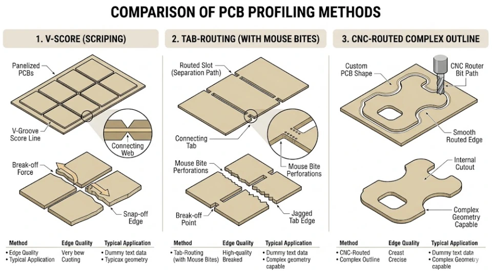
Best fit for curved or irregular contours, notches, internal cutouts and edges that need a machined finish. The router path needs tool access, a defined kerf and suitable support; final tolerance is confirmed per material, thickness and geometry.

Complex outlineCutoutsMachined edge
Efficient for straight arrays

V-Score / V-Cut

0.3–0.5 mm
Typical residual-web discussion

Best fit for rectangular boards with uninterrupted straight separation lines. It can improve panel utilization, but the break operation bends the panel and leaves a scored edge. Score geometry and residual web must be released for the actual board thickness and assembly risk.

Straight linesRectangular arraysBreakaway edge

Tab Routing + Mouse-Bite

0.5–0.6 mm
Typical hole diameter

Best fit when an irregular board must remain attached to rails through printing, placement, reflow or inspection. Tab position controls panel stiffness and local breakout risk. Small nubs can remain and may need a finishing allowance.

Irregular boardsSMT supportPlaced tabs

Laser Depaneling

Non-contact
No cutting-tool contact

Consider for flexible, thin, brittle or densely populated designs where mechanical contact is undesirable. Laser feasibility still depends on material absorption, thickness, heat-affected-zone limits, cleanliness and the required edge condition; it is not an automatic substitute for DFM.

Flex / thinDense edgeThermal review

Do Not Release a Universal Component-to-Edge Rule

Component clearance must be set from the board thickness, copper distribution, package sensitivity, component orientation and separation method. For assembled panels with edge-adjacent MLCCs, BGAs, QFNs, sensors or connectors, provide the assembly drawing and request a method-specific keep-out or strain-validation plan rather than relying on one generic distance.

Buyer Decision Asset

Board Condition → Process Route → RFQ Input → Release Evidence

Use these matrices to turn an outline request into a controlled manufacturing requirement. Values marked typical are starting points for DFM, not blanket capability guarantees.

Board or Panel ConditionLikely RoutePrimary ConstraintRelease Check
Rectangular array with straight break linesV-score, or hybrid V-score + routingBreakaway strain, residual web, edge appearanceScore position and residual-web measurement; panel break trial when required
Curved outline, notch or internal windowCNC routingTool diameter, corner radius, support and kerfFirst-piece outline and cutout measurement against mechanical drawing
Irregular board assembled in panelTab routing with mouse-bitesTab location, panel rigidity and nub allowancePanel handling trial, tab geometry review and post-break edge inspection
Thin, flexible, brittle or edge-dense designLaser feasibility review or supported low-stress routingMaterial response, thermal effect, fixturing and contaminationEdge inspection plus dimensional, cleanliness or strain evidence as specified
Castellated module edgePlated-hole process followed by controlled routingHole position, plating continuity and breakout geometryCastellation visual inspection and dimensional check to the released drawing
Card-edge connectorProfile routing plus drawing-controlled bevelBevel angle/depth, board thickness and hard-gold regionBevel dimension and edge-condition inspection; coating evidence if requested
RFQ InputWhy It Changes the RouteEvidence to Request
Gerber or IPC-2581 + mechanical outlineDefines the controlling contour, cutouts, slots and plated-edge featuresCAM/DFM findings and released panel or profile drawing
Material, stack-up, copper and finished thicknessChanges stiffness, cutting response, score geometry and achievable toleranceMaterial confirmation and agreed outline tolerance
Assembly drawing + edge-component locationsShows packages exposed to board flex, vibration, dust or thermal effectsKeep-out review, fixture concept and strain plan when applicable
Panel rails, fiducials, tooling holes and conveyor limitsControls assembly-line handling and post-assembly machine alignmentApproved panel drawing and first-panel fit check
Finished-edge and enclosure requirementsDetermines whether a scored edge, tab remnant or machined edge is acceptableVisual standard, key-dimension report or mating-fit sample as specified
Inspection and documentation requirementSets the release package before production rather than after shipmentFAI dimensions, edge photos, traveler/lot data or customer-specific report

Preliminary design values commonly discussed for standard rigid-board panels include a CNC outline target around ±0.1 mm, V-score residual web around 0.3–0.5 mm, mouse-bite holes around 0.5–0.6 mm diameter at 0.75–1.0 mm pitch, and routed internal cutouts from about 1.0 mm width. Every value requires confirmation for the selected material, thickness, geometry and production route.

Feature Control

How Specialty PCB Edge Features Are Released

Special edge features need sequencing and inspection requirements in the fabrication data. They should not be inferred from the board image or assembly BOM.

01

Complex Contours and Internal Cutouts

CNC routing supports curves, notches and windows, but the smallest tool that can enter the feature sets the internal radius and practical width. Call out controlling dimensions, datum scheme, corner radii and whether the cutout is plated or non-plated. A 1.0 mm minimum cutout is a preliminary reference only; CAM confirms access and tolerance for the actual construction.

02

V-Score Geometry

V-score is defined by line position, groove angle, depth or residual web, board thickness and the permitted break condition. The same residual web does not produce the same break force on every laminate. Put the score line on the mechanical or panel drawing and agree how it will be measured before production release.

03

Breakaway Tabs and Mouse-Bites

Tabs hold the array through assembly and transport. Their count and placement must balance stiffness with low-risk separation, keeping breakout locations away from sensitive packages and function-critical edges. Typical mouse-bite discussions start around 0.5–0.6 mm holes at 0.75–1.0 mm pitch, then change with tab width and required break force.

04

Castellated and Edge-Plated Features

Castellated contacts begin as plated holes positioned on the final routed edge. The drawing should identify hole diameter, pitch, finished module outline, pad geometry, plating/finish requirement and acceptable breakout. Release inspection can include visible wall coverage, burr/smear condition and critical dimensions without claiming the module's final solder-joint performance.

05

Gold-Finger Bevels and Chamfers

A card-edge bevel must follow the connector drawing, not a generic angle. Provide the insertion edge, finished thickness, bevel angle and depth, hard-gold region and any no-bevel areas. Common 20° or 30° requests can be reviewed, but the production value and inspection method are released per connector and board design.

06

Laser Feasibility for Sensitive Designs

Laser is a non-contact option for selected flex, rigid-flex, thin or brittle constructions. DFM still checks wavelength/material interaction, thickness, copper near the cut, heat-affected-zone limits, debris control and edge appearance. If laser is not the appropriate route, CAM can compare supported mechanical separation and fixture strategies.

Panel Design

Panelization Must Serve Fabrication, Assembly and Separation

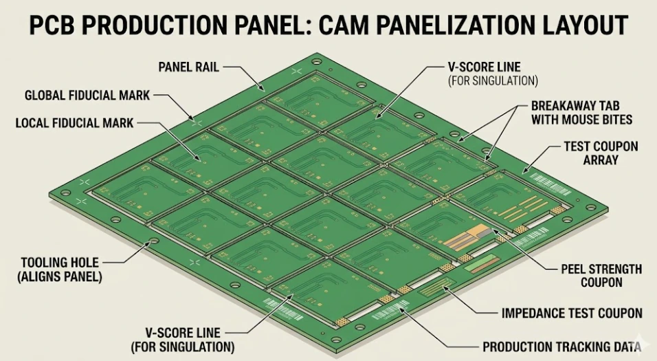
Panelization groups boards into a format that can be fabricated, printed, placed, reflowed, inspected and separated repeatably. The best array is therefore not always the one with the highest board count. It must preserve rail support, tooling access, fiducial visibility, coupon space, board orientation and a separation path that does not load sensitive components.

Rails, fiducials and tooling references
Provide the assembler's conveyor width, required rail width, tooling-hole convention and global/local fiducial rules. A 5 mm rail or 1.0 mm fiducial may be a useful starting discussion, but the assembly partner's equipment and stencil/fixture plan control the released panel. Bad-mark areas, barcodes, coupons and traceability markings also consume rail space and should be included before array optimization.

Array orientation and mixed constraints
CAM should compare board rotation, routing kerf, score-line continuity and copper/thermal balance. V-score can place straight-edged boards close together, while routed arrays need cutter access and tabs. For boards with overhanging connectors, tall parts or selective-solder fixtures, assembly clearance can be more important than laminate utilization.

Breakaway details
Place tabs symmetrically enough to survive handling, but not on flex transitions, controlled connector edges or next to strain-sensitive packages. Treat 0.5–0.6 mm mouse-bite holes and 0.75–1.0 mm pitch as provisional inputs. Final tab width, hole count, breakout direction and nub allowance belong on the approved panel drawing.


CAM panelization drawing with assembly and depaneling controls

Design Scenarios

Common PCB Profiling and Depaneling Scenarios

These scenarios show why the board condition—not an industry label—should determine the separation route and evidence package.

Straight Rectangular Array

V-Score With Controlled Break Conditions

Use when all separation lines are straight and the scored edge is acceptable. Confirm residual web, board thickness, component keep-out, breakout direction and whether separation is manual, fixture-assisted or automated.

Enclosure-Critical Outline

CNC Routing With Datum-Based Inspection

Use for contours, mounting features and cutouts that must fit a housing. Identify the controlling datums and critical dimensions so the release report measures what affects fit instead of only reporting a generic outline tolerance.

SMT Panel Retention

Tab Routing Around Assembly Risks

Use when irregular boards need rails and support through assembly. Tab placement should protect edge packages, maintain stiffness through reflow and leave remnants only where the finished product can accept them.

Module Board

Castellations Integrated With the Profile

Coordinate plated-hole location, routing centerline, module outline and surface finish. The motherboard land pattern and solder-joint acceptance remain system-level design responsibilities, while the PCB release covers the fabricated edge feature.

Thin or Edge-Dense Assembly

Non-Contact or Supported Low-Stress Review

Compare laser feasibility, routed-tab removal and dedicated support fixtures when the board is flexible, brittle or populated near the separation line. Validate the chosen route rather than calling any method inherently risk-free.

Metal, RF or Mixed Material

Material-Specific Edge Acceptance

Metal-core, PTFE-based, rigid-flex and ceramic constructions respond differently to cutting. Release criteria may need to address burrs, smear, fiber pull-out, delamination, chipping, thermal effects or transition-zone damage.

Design and RFQ Guide

What Engineering Must Define Before PCB Profiling

1. Supply One Controlling Outline

Send Gerber or IPC-2581 data with a dedicated mechanical outline, dimensioned drawing and revision. Remove duplicate or conflicting outline layers. Mark routed slots, V-score lines, plated slots, non-plated cutouts, castellations and bevel edges distinctly so CAM can assign the correct sequence.

2. State the Downstream Assembly Flow

Identify whether boards ship loose, remain panelized for SMT, pass through wave or selective soldering, use a test fixture, or are depanelled after final inspection. Provide conveyor, rail, component-height and fixture constraints. These inputs often decide between V-score, tab routing and a supported post-assembly route.

3. Define the Finished Edge and Release Package

Separate cosmetic, enclosure-fit and electrical edge requirements. State which dimensions are critical, whether tab nubs or score texture are acceptable, and whether you need first-article dimensions, edge photos, lot traceability, strain evidence or a customer-specific inspection report.

A usable profiling package identifies the controlling geometry and the downstream process. If CAM has to guess the datum, panel rail, break line or acceptable edge condition, the quotation may be fast but the production release is still incomplete.

How to Control Post-Assembly Depaneling Risk

Fixture and Alignment Inputs

For routed or automated separation, define how the panel and individual boards are supported, how tooling or optical references locate the cut, where dust extraction is permitted and how separated boards are handled. Fiducials help only when their size, keep-out and coordinate relationship match the selected machine and released panel data.

Strain-Sensitive Components

Flag MLCCs, BGAs, QFNs, sensors, crystals, connectors and large packages close to break lines. Increase keep-out where design permits, orient susceptible components thoughtfully and avoid unsupported manual bending. When product risk warrants it, define strain-gage validation using a customer limit or an agreed IPC/JEDEC-9704 test approach.

Post-assembly separation can transfer bending, vibration or local fixture load into solder joints and ceramic packages. The risk depends on the complete assembly, not only the bare-board outline. Method selection should therefore be part of panel and component-placement review before stencil, fixture or automation decisions are frozen.

PCB Profiling Inspection and Standards Boundary

APTPCB can release profiling against the approved mechanical drawing and the customer-specified acceptance class. Relevant references may include IPC-A-600 for bare-board acceptability, IPC-6012 for rigid-board performance requirements, IPC-2221/IPC-2222 for design context, IPC-A-610 for the assembled board, and IPC/JEDEC-9704 when assembly strain measurement is required. The purchase order and released drawing must identify the applicable revision, class and customer-specific limits. Inspection may include first-piece outline dimensions, cutout/slot dimensions, V-score geometry, tab condition, bevel geometry, edge photos and evidence for castellated or plated-edge features. These checks verify the PCB/PCBA manufacturing result; final enclosure fit, connector life and product reliability remain system-level validation responsibilities.

Material Decision Table

How Substrate Choice Changes PCB Profiling

Material families differ in stiffness, abrasiveness, thermal response and edge-failure mode. The route is released only after laminate type, thickness and copper construction are known.

SubstratePrimary Edge RiskProcess ReviewBuyer Input / Release Check
Standard or high-Tg FR-4Fiber pull-out, resin smear, delamination or tool-wear driftCNC, V-score or tab route according to outline and assemblyLaminate, thickness, outline tolerance; inspect dimensions and edge condition
PTFE / RF laminateSoft matrix smear, copper overhang or layer-edge damageMaterial-specific routing and support; laser only after feasibility reviewExact laminate and RF edge constraints; inspect smear, overhang and delamination
Aluminum or copper-core PCBMetal burrs, smear and dielectric-interface damageMetal-compatible routing or scoring with deburr controlBase-metal thickness and seating surface; inspect burr and interface condition
Polyimide flexTearing, stretching, debris or thermal edge effectsLaser feasibility or supported precision cuttingFlex construction and coverlay; inspect contour, edge and residue
Rigid-flexDamage or delamination near the rigid-to-flex transitionRoute sequence and support kept away from transition zonesTransition geometry and bend area; inspect transition integrity
CeramicChipping and crack initiation from mechanical or thermal loadSpecialized machining or laser/scribe review by ceramic typeMaterial, thickness and allowed chip limit; magnified edge inspection

Do not transfer a routing tolerance or separation rule from one substrate family to another. Minimum features, tool access, edge acceptance and evidence are confirmed during CAM review.

After Reflow and Inspection

Post-Assembly Separation Is a PCBA Process Step

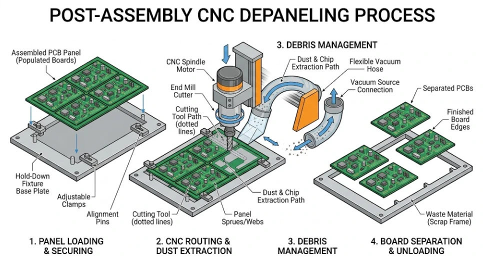
Once components are soldered, depaneling must protect the assembly as well as the board outline. The approved method should state how the panel is supported, how the separation path is located, how debris is controlled and what happens to each board after it is released.

Manual or fixture-assisted V-score separation
Suitable only when the panel, component placement and product risk permit the bending load. Define breakout direction and support. Do not use an arbitrary volume threshold to justify manual separation; use a documented risk and repeatability decision.

Routed tab removal
A supported fixture can limit board movement while tabs are cut. Review cutter access, local package clearance, dust extraction and board pickup. A machined process reduces uncontrolled snapping, but it does not remove all vibration or fixturing risk.

Laser separation
A laser avoids cutting-tool contact and can suit selected thin, flexible or edge-dense assemblies. The process still needs material, thermal-effect, fume/debris and edge-quality review. Call it non-contact—not zero-risk—and define the evidence required for the actual product.

Controlled post-assembly PCB depaneling with fixture and edge-risk management

Cost Without False Savings Claims

Reduce Profiling Cost by Removing Constraints, Not Evidence

The unit cost is shaped by boards per panel, routing distance, tool changes, specialty edge steps, fixture needs, inspection and post-assembly handling. A lower-cost route is useful only if it still meets edge, fit and reliability requirements.

Compare Array Orientations

Ask CAM to compare board rotation and hybrid score/routing layouts. Small outline changes can sometimes improve panel fit, but no percentage saving should be promised until the released board size and production panel are nested.

Separate Functional From Cosmetic Edges

Reserve tighter tolerances, nub removal, bevels and special inspection for the edges that affect connectors, housings or customer appearance. Applying the strictest requirement to every edge increases machining and inspection without improving function.

Freeze the Data Package Before Tooling

Conflicting outline layers, late rail changes and missing assembly constraints create re-CAM, fixture and schedule cost. A revision-controlled panel drawing and evidence list reduce those avoidable changes.

Cost DriverEngineering QuestionPractical Action
Panel utilizationCan board rotation or straight-line scoring improve the array?Compare released nests, not generic savings percentages
Routing length and cutoutsWhich contours and windows are functionally necessary?Simplify geometry where mechanical design permits
Tab finishingWhere are remnants acceptable or enclosure-critical?Place tabs on non-critical edges and define nub allowance
Special edge featuresWhich castellations, bevels or plated slots are required?Call out only functional features with controlled drawings
Post-assembly separationWhat support, cleanliness and strain controls are needed?Select the process before assembly tooling is released
Release evidenceWhich dimensions and records reduce buyer risk?Request a right-sized report rather than deleting inspection

Get a Route Comparison With Your Quote

Send the board outline, material, thickness, panel/assembly constraints and finished-edge requirement. Where more than one route is practical, ask for the trade-off between panel utilization, tooling, edge result, assembly risk and release evidence.

FAQ

PCB Depaneling and Profiling Questions

What is the difference between PCB profiling and depaneling?
PCB profiling creates the finished board outline during bare-board fabrication. PCB depaneling separates individual boards from an assembly panel, often after soldering and inspection. The same route families may be used, but post-assembly depaneling requires added control of board flex, component clearance, fixturing and contamination.
How do I choose between CNC routing, V-score, tab routing and laser depaneling?
Use V-score for straight separation lines and efficient rectangular arrays; CNC routing for complex contours, cutouts and cleaner finished edges; tab routing when an irregular board must remain supported through assembly; and laser when a non-contact process is justified by thin, flexible, brittle or densely populated designs. The final route must be confirmed against material, thickness, component position, edge finish, volume and assembly method.
Is V-score or tab routing better for an SMT panel?
V-score is usually the simpler choice for rectangular boards with uninterrupted straight break lines. Tab routing is more flexible for curved or irregular outlines and lets CAM place support tabs around the panel. The better option is the one that maintains panel rigidity, protects edge-adjacent components and produces the required finished edge after separation.
How much component clearance is needed from a PCB depaneling line?
There is no universal clearance that is safe for every stack-up and component. Clearance depends on the separation method, board thickness, copper distribution, component orientation, package sensitivity and whether separation occurs before or after assembly. Send the assembly drawing and edge-component locations so DFM can set the keep-out and, when required, define a strain-validation plan.
What mouse-bite and V-score values should I put in the fabrication drawing?
As preliminary design inputs, mouse-bite holes are often discussed around 0.5–0.6 mm diameter and 0.75–1.0 mm pitch, while a V-score residual web may be discussed around 0.3–0.5 mm. These are not automatic release values. APTPCB confirms the final tab width, hole pattern, score geometry and residual web during DFM for the actual material, thickness, panel rigidity and breakaway requirement.
Can profiling include castellated holes, internal cutouts and gold-finger bevels?
Yes, when those features are defined in the fabrication data and are compatible with the selected stack-up and process route. Castellations require plated holes positioned on the routed edge; internal cutouts require tool-access and corner-radius review; and card-edge bevels require the connector drawing, bevel angle, depth and hard-gold requirements. Availability and tolerances are confirmed during DFM.
What should I send for a PCB profiling and depaneling quote?
Send Gerber or IPC-2581 data, the mechanical outline, stack-up and material, finished thickness, board and panel dimensions, quantity, assembly drawing, component-to-edge locations, preferred separation method, rail and fiducial requirements, cutouts, slots, castellations, bevel details and any inspection, strain or release-document requirements. If the method is undecided, identify the assembly flow and finished-edge requirement so CAM can compare routes.

International RFQ Coordination

One Profiling Data Package for Distributed Teams

APTPCB accepts international PCB and PCBA RFQs. Use revision-controlled files, metric dimensions and explicit release requirements so engineering, procurement and assembly teams review the same panel definition.

North America
Engineering and procurement handoff

Share the controlling mechanical drawing, assembly-panel constraints and required inspection records. Time zone, freight and import requirements are confirmed during quotation rather than embedded as unsupported lead-time promises.

Revision controlRFQ packageRelease evidence
Europe
Metric drawings and standard revisions

State dimensions in millimetres, the applicable IPC revision/class and any customer-specific acceptance limit. Certification or regulatory requirements must be verified against the current certificate and scope before supplier approval.

Metric dataIPC scopeSupplier review
Asia-Pacific
Fabrication-to-assembly alignment

Keep the PCB outline, panel drawing, stencil/fixture constraints and post-assembly separation route under one revision so factory and assembly teams do not optimize against different panel definitions.

Panel drawingAssembly flowChange control
Other Regions
Commercial and logistics confirmation

Provide destination, quantity, packaging and documentation needs with the technical RFQ. Shipping route, incoterms, timing and any destination-specific documents are confirmed in the formal quotation.

DestinationPackagingQuotation

Get a DFM-Reviewed PCB Profiling Route

Upload the outline, stack-up, material, assembly drawing, panel constraints and finished-edge requirements. APTPCB will review the practical route, identify missing release inputs and quote against the agreed scope without inventing a universal depaneling rule.

Discuss the Panel With Engineering