Reliable from Prototype to Production

FR-4 PCB Manufacturing

Standard, high-Tg, and low-loss FR-4 stackups with HDI microvias, ±5% impedance, and IPC-6012 Class 3 inspection keep multilayer boards on schedule and within budget.

  • 1-40 layers
  • Standard & high-Tg laminates
  • Low-loss FR-4 up to 25 Gbps
  • HDI microvias ≤75 μm
  • ±5% impedance coupons
  • IPC-6012 Class 3
  • 12-hour quick-turn

Get an Instant Quote

Full Quote →

FR-4 PCB Fabrication & Assembly

APTPCB engineers recommend stackups spanning standard Tg 135 °C through high-Tg 175 °C and low-loss FR-4 for 10–25 Gbps signals, balancing cost, Tg, and Dk/ Df requirements.

We manage HDI microvias, sequential lamination, and controlled-dielectric spacing so BGAs, press-fit connectors, and impedance-controlled nets stay within tolerance.

Assembly support covers lead-free reflow, selective solder, conformal coating, and testing so FR-4 prototypes and volume builds run through one workflow.

FR-4 fabrication line and assembly support

FR-4 Programs Delivered

Representative telecom, automotive, industrial, and consumer builds on FR-4 and high-Tg platforms.

Telecom line cards

Telecom line cards

Automotive control units

Automotive control units

Industrial automation controllers

Industrial automation controllers

Aerospace avionics backplanes

Aerospace avionics backplanes

Consumer electronics motherboards

Consumer electronics motherboards

Medical imaging electronics

Medical imaging electronics

IPC-6012 Class 3 • Automotive / Aerospace Ready

Stackups are validated with impedance coupons, CAF testing, thermal stress, and AOI/X-ray inspections, ensuring FR-4 boards survive multi-reflow and harsh duty cycles.

Download Stackup Guide
Standard FR-4High-Tg FR-4Low-loss FR-4HDI microvias±5% impedance12-hour expedite

APTPCB FR-4 Manufacturing Services

Complete FR-4 solutions from quick-turn prototypes to Class 3 production with HDI, impedance, and mixed-signal routing.

FR-4 PCB Types

Standard multilayer, high-Tg, low-loss, HDI, and rigid-flex hybrids based on FR-4 cores.

  • Standard Multilayer – 4–12 layers for control and consumer electronics.
  • High-Tg Multilayer – 8–20 layers for automotive and industrial controllers.
  • HDI 1+N+1 – Fine-pitch BGA breakout with microvias and buried vias.
  • Low-Loss FR-4 – Df 0.009–0.012 for 10–25 Gbps links.
  • Rigid-Flex Hybrids – FR-4 cores with polyimide flex for compact assemblies.

Via Structures & Interconnects

  • Microvias & Via-in-Pad: Laser-drilled vias ≤75 μm for HDI fan-out.
  • Buried & Blind Vias: Connect dense inner layers without full-depth drilling.
  • Backdrilled Vias: Remove stubs on high-speed backplanes.
  • Resin-Filled Vias: Maintain planarity for fine-pitch BGAs.
  • Thermal Via Arrays: Pull heat into copper planes or heatsinks.

Sample FR-4 Stackups

  • 8-Layer Standard: 1 oz outer, 0.5 oz inner with 370HR prepregs.
  • 12-Layer HDI: 1+N+1 microvia design on IT-180A.
  • 18-Layer Low-Loss: EM-370 + low-roughness copper for 25 Gbps SERDES.

Material & Design Guidelines

Select Tg/Df combinations, copper weights, and prepreg styles aligned to thermal and SI budgets.

  • Document Tg, Dk/Df, copper weights, and dielectric thickness for each layer.
  • Balance copper to avoid bow/twist and meet Class 3 requirements.
  • Specify soldermask color/finish pairs that support impedance and coating.
  • Call out CAF mitigation spacing where humidity or voltage are high.

Reliability & Validation

Thermal shock, CAF, impedance coupons, AOI, X-ray, and flying-probe testing are available per lot to prove FR-4 boards meet automotive and aerospace expectations.

Cost & Application Guidance

  • Tiered Materials: Reserve low-loss laminates only for high-speed layers.
  • Panel Optimization: Share panel sizes across related products.
  • Finish Planning: Use ENIG/OSP combos to balance cost and solderability.

FR-4 PCB Manufacturing Flow

1

Stackup & DFx Review

Align Tg, Df, and copper counts with performance targets.

2

Imaging & Drilling

LDI imaging and tight drill control for microvias and fine traces.

3

Sequential Lamination

Controlled cycles for HDI and high-layer builds.

4

Plating & Fill

Copper fill for vias, via-in-pad, and buried structures.

5

Surface Finish & Assembly Prep

ENIG/ENEPIG/OSP plus bake schedules for lead-free reflow.

6

Testing & Validation

Impedance coupons, electrical tests, AOI/X-ray, and reliability data.

CAM Engineering Checklist

DFx reviews lock dielectric targets, copper balance, and impedance models before fab.

  • Confirm materials (Tg/Df) and acceptable alternates.
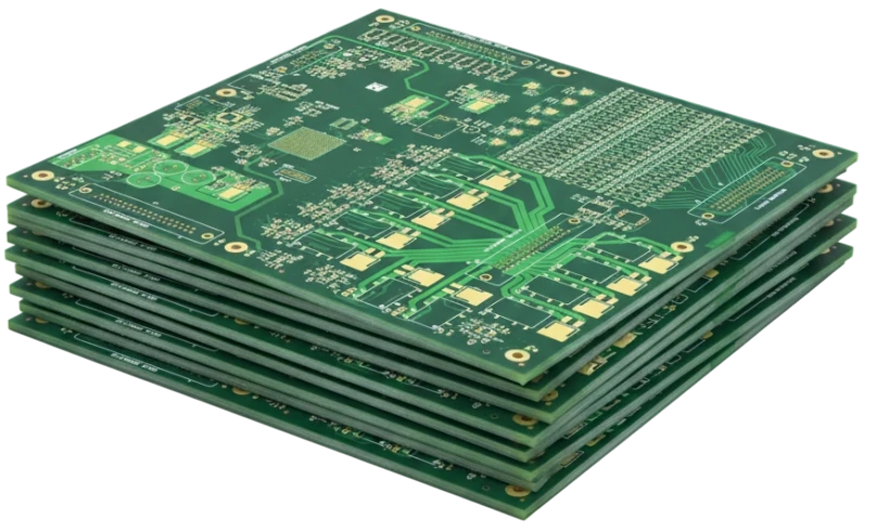
  • Define lamination schedule and sequential build requirements.
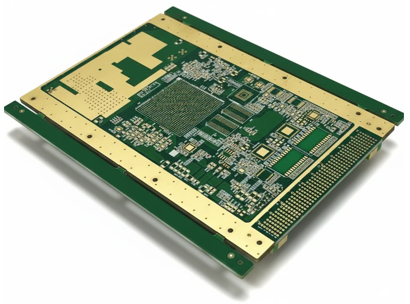
  • Model impedance and include coupon references.
  • Specify via fill, backdrill, and depth control where needed.
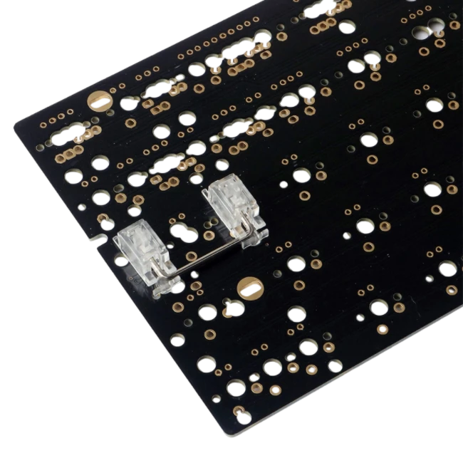
  • Detail finish, mask, and coating keep-outs.
  • Document bake/handling instructions for high-Tg builds.

Production Checklist

SPC-monitored lamination, drilling, plating, and inspection feed data back to design teams.

  • Monitor lamination pressure/temperature.
  • Inspect drill quality, plating thickness, and via fill.
  • Validate impedance coupons and electrical tests.
  • Perform AOI, X-ray, and micro-section analysis.
  • Archive reliability data (CAF, thermal shock) as required.
  • Package boards with humidity control and flatness supports.
1–40

Layer Count

Sequential lamination for complex builds

3/3 mil

Standard Line/Space

2/2 mil available on request

±5%

Impedance Control

TDR-verified per lot

1100×500 mm

Max Panel

Suitable for backplanes and LED panels

Advantages of FR-4 PCBs

Flexible materials, proven reliability, and broad capability.

Versatile Stackups

Standard through HDI and rigid-flex configurations.

Class 3 Quality

Meets automotive/aerospace reliability standards.

Signal Integrity

Low-loss options + ±5% impedance for 25 Gbps designs.

Rapid Turnaround

12-hour expedite for urgent prototypes.

Cost Effective

Optimized stackups lower BOM and assembly spend.

Documentation

Complete testing packages accelerate approval.

Process Stability

Standardized lamination, bake, and inspection recipes reduce variance from prototype through mass production.

SI Proof Pack

Coupons, TDR/eye or S-parameter data keep high-speed FR-4 launches predictable.

Why Choose APTPCB?

FR-4 platforms balance performance and cost while supporting HDI, high-speed, and high-Tg requirements.

TelecomAutomotiveIndustrialAerospaceConsumerMedical
APTPCB production line
FR-4 production lines • HDI microvias • Impedance labs

FR-4 PCB Applications

Telecom infrastructure, automotive electronics, industrial automation, aerospace avionics, consumer and medical products all rely on FR-4.

Available in standard, high-Tg, and low-loss versions to match your environment.

Telecom & Network

Baseband, switch, and optical control cards.

BasebandSwitchRouterOptical

Automotive & EV

ECUs, ADAS, battery management, and infotainment.

ECUADASBMSInfotainment

Industrial Automation

Robotics, PLC, and power controllers.

RoboticsPLCPower modules

Aerospace & Defense

Mission computers, avionics, and radar control.

AvionicsMission computerRadar

Medical & Life Sciences

Imaging, monitoring, and diagnostic platforms.

ImagingMonitoringDiagnostics

Consumer & IoT

Wearables, smart devices, and computing modules.

WearablesSmart homePC

Test & Measurement

Instrumentation and load boards.

InstrumentationATELoad boards

Data Center & AI

Server management and power distribution.

ServerPowerAI accelerators

FR-4 Design Challenges & Solutions

Handle Tg selection, impedance control, CAF avoidance, and HDI manufacturability with confidence.

Common Design Challenges

01

Material Selection

Choosing between standard, high-Tg, and low-loss laminates impacts cost and performance.

02

Impedance Control

Uncompensated stackups cause skew and reflection issues.

03

CAF Mitigation

Dense vias and humidity can create conductive anodic filaments.

04

HDI Manufacturability

Overly aggressive design rules reduce yield.

05

Lead-Free Thermal Stress

Multiple reflow cycles require resin-filled vias and high-Tg materials.

06

Documentation & Testing

Missing validation slows automotive/aerospace approval.

Our Engineering Solutions

01

Material Playbooks

We recommend Tg/Df tiers and acceptable substitutes per product.

02

Impedance Modeling

Stackups are simulated and coupon data archived for ±5% control.

03

CAF Controls

Spacing, resin fill, and bake cycles mitigate CAF risk.

04

HDI Rule Guidance

Design kits specify drill sizes, capture pads, and tolerances.

05

Thermal Stress Testing

T260/T288 and thermal shock verify build robustness.

How to Control FR-4 PCB Cost

Lock procurement strategy before design freezes—align laminate ladders, finish preferences, and MOQ per product family while making demand visible (forecast ladders, MP schedule, safety stock) so we can secure copper, resin, and specialty films at tiered pricing. When sourcing requirements, impedance specs, and qualification cadence are transparent, we can negotiate better supply terms and keep FR-4 unit costs predictable.

01 / 08

Laminate Ladder Contracts

Map each program to A/B/C laminate sets with published lead time, MOQ, and alternates.

02 / 08

Supplier Collaboration Windows

Book shared sourcing reviews (BOM + AVL) so component procurement stays synced with board fab slots.

03 / 08

DFx + Procurement Sync

Run DFx checkpoints with sourcing present to agree on stackups, finishes, and alternates before release.

04 / 08

Forecast & Safety Stock

Share 3–6 month demand ladders so we can preload copper, prepregs, and films to avoid spot buys.

05 / 08

MOQ / Consolidated Shipments

Combine SKUs per dispatch lane to hit freight and customs breakpoints.

06 / 08

Lead Time Governance

Maintain shared dashboards for copper, laminate, and finish lead times so PO release dates stay ahead of constraints.

07 / 08

Frame Agreements

Use quarterly volume commitments to unlock rebate tiers on FR-4 cores, surface finish chemistry, and solder mask.

08 / 08

Qualification Bundles

Plan PPAP/FAI lots across programs so reliability coupons and reports are reused.

Certifications & Standards

Quality, environmental, and industry credentials supporting reliable manufacturing.

Certification
ISO 9001:2015

Quality management across multilayer FR-4 production.

Certification
ISO 14001:2015

Environmental compliance for plating, etching, and lamination.

Certification
ISO 13485:2016

Medical PCB traceability and cleanliness requirements.

Certification
IATF 16949

Automotive PPAP, SPC, and CAPA coverage.

Certification
AS9100

Aerospace process control and documentation.

Certification
IPC-6012 Class 2/3

Performance specification for rigid PCBs.

Certification
UL 796 / UL 94 V-0

Safety and flammability certifications.

Certification
RoHS / REACH

Hazardous substance compliance.

Selecting an FR-4 Manufacturing Partner

  • Material sourcing agreements for standard, high-Tg, and low-loss FR-4.
  • HDI microvia, sequential lamination, and impedance modeling capability.
  • Comprehensive inspection (AOI, X-ray, flying probe).
  • Lead-free assembly and coating support.
  • Automotive/aerospace documentation packages.
  • 24-hour DFx feedback across CAM, SI, and manufacturing teams.
Engineers reviewing FR-4 stackups

Quality & Cost Console

Process & Reliability Controls + Economic Levers

Unified dashboard connecting HDI quality checkpoints with the economic levers that compress cost.

Process & Reliability

Pre-Lamination Controls

Stack-Up Validation

  • Panel utilization+5–8%
  • Stack-up simulation±2% thickness
  • VIPPO planningPer lot
  • Material bake110 °C vacuum

Pre-Lamination Strategy

• Rotate outlines, mirror flex tails

• Share coupons across programs

• Reclaim 5-8% panel area

Registration

Laser & Metrology

Registration

  • Laser drill accuracy±12 μm
  • Microvia aspect ratio≤ 1:1
  • Coverlay alignment±0.05 mm
  • AOI overlaySPC logged

Laser Metrology

• Online laser capture

• ±0.05 mm tolerance band

• Auto-logged to SPC

Testing

Electrical & Reliability

Testing

  • Impedance & TDR±5% tolerance
  • Insertion lossLow-loss verified
  • Skew testingDifferential pairs
  • Microvia reliability> 1000 cycles

Electrical Test

• TDR coupons per panel

• IPC-6013 Class 3

• Force-resistance drift logged

Integration

Assembly Interfaces

Integration

  • Cleanroom SMTCarrier + ESD
  • Moisture control≤ 0.1% RH
  • Selective materialsLCP / low Df only where needed
  • ECN governanceVersion-controlled

Assembly Controls

• Nitrogen reflow

• Inline plasma clean

• 48h logistics consolidation

Architecture

Stack-Up Economics

Architecture

  • Lamination cyclesOptimize 1+N+1/2+N+2
  • Hybrid materialsLow-loss where required
  • Copper weightsMix 0.5/1 oz strategically
  • BOM alignmentStandard cores first

Cost Strategy

• Balance cost vs performance

• Standardize on common cores

• Low-loss only on RF layers

Microvia Planning

Via Strategy

Microvia Planning

  • Staggered over stacked-18% cost
  • Backdrill sharingCommon depths
  • Buried via reuseAcross nets
  • Fill specificationOnly for VIPPO

Via Cost Savings

• Avoid stacked microvias

• Share backdrill tools

• Minimize fill costs

Utilization

Panel Efficiency

Utilization

  • Outline rotation+4–6% yield
  • Shared couponsMulti-program
  • Coupon placementEdge pooled
  • Tooling commonalityPanel families

Panel Optimization

• Rotate for nesting efficiency

• Share test coupons

• Standardize tooling

Execution

Supply Chain & Coating

Execution

  • Material poolingMonthly ladder
  • Dual-source PPAPPre-qualified
  • Selective finishENIG / OSP mix
  • Logistics lanes48 h consolidation

Supply Chain Levers

• Pool low-loss material

• Dual-source laminates

• Match finish to need

FR-4 PCB Manufacturing — Upload Data for DFx Review

Talk to FR-4 Engineers
IPC Class 3 manufacturing
HDI & low-loss expertise
1–40 layer capability
Reliability data packaged

Share stackups, impedance targets, and schedule—we reply with DFx notes, cost, and lead time within one business day.

FR-4 PCB FAQ

Common questions about materials, impedance, and reliability.