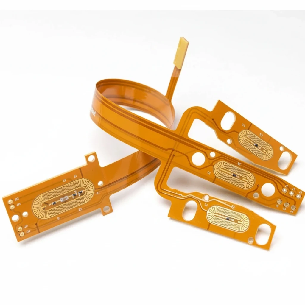
Mixed SMT and through-hole PCB assembly evaluated for selective soldering

Process selection before production promises

PCB Selective Soldering for SMT/THT PCBA

PCB selective soldering is a localized assembly process for soldering defined through-hole pins on a board that may already contain reflowed SMT components. Its success depends on nozzle access, flux activation, preheat, contact time, thermal mass, solderability, board support, and agreed acceptance evidence—not on a generic promise of precision. APTPCB reviews these inputs before confirming the process route, inspection plan, and quote.

Get an Instant Quote

Mixed SMT/THTBest fit
Nozzle path + clearanceDFM focus
Preheat + contact timeThermal control
Deposit + activationFlux control
Bridges + hole fillPrimary risks
IPC / customer criteriaAcceptance
Visual / AOIVisible joints
As specifiedHidden evidence
ICT / FCT by planElectrical release
Revision-controlled dataQuote basis
Mixed SMT/THTBest fit
Nozzle path + clearanceDFM focus
Preheat + contact timeThermal control
Deposit + activationFlux control
Bridges + hole fillPrimary risks
IPC / customer criteriaAcceptance
Visual / AOIVisible joints
As specifiedHidden evidence
ICT / FCT by planElectrical release
Revision-controlled dataQuote basis

Where selective soldering fits in a mixed-technology PCBA

Selective soldering is most useful after SMT reflow when only defined connectors, relays, terminals, transformers, shields, or other through-hole parts still require solder. The localized process avoids exposing the whole solder side to a conventional wave, but it does not automatically make every dense layout solderable.
The first engineering question is access. A viable path needs room for the nozzle and solder flow, clearance from component bodies and previously reflowed joints, stable board support, and enough heat transfer for the pin, barrel, pad, and connected copper. If one of those conditions cannot be controlled, manual soldering, pin-in-paste, a pallet-assisted wave route, or a layout change may be the better decision.

Four release gates from RFQ to repeat production

A selective soldering quote should define what must be true at each gate. This prevents a production price from being mistaken for process approval.
Gate 1 — RFQ completeness: revision-aligned fabrication and assembly data, connector details, pin finish and protrusion, copper and thermal information, chemistry restrictions, acceptance class, test scope, and required shipment records are available.
Gate 2 — DFM feasibility: the proposed nozzle path, keep-outs, component heights, board support, thermal relief strategy, solder mask condition, and cleaning route have no unresolved blocker. Any assumption is recorded for customer confirmation.
Gate 3 — First-article release: the approved program and material revision are linked to joint inspection, evidence for hidden or high-thermal-mass locations when specified, residue disposition, repair records, and the agreed ICT or FCT result.
Gate 4 — Production release: recipe and revision control, defect reaction limits, sampling or inspection scope, traceability, change control, and the shipment data package are agreed. A route remains blocked when solderability, the thermal window, access, or acceptance evidence is unresolved.

Selective soldering must connect to the full assembly route

A reliable selective soldering plan starts upstream. Hole and pad geometry, solder mask, copper connections, component finish, storage history, insertion condition, and SMT-side layout all affect whether the final through-hole joint can be formed and inspected.
Before soldering: verify revision consistency, component and board solderability risks, polarity and insertion requirements, underside access, and any temperature limit stated by the component owner.
During process definition: match flux chemistry and application to preheat, solder contact, cleaning, coating, and reliability requirements. No-clean is not a synonym for “no residue decision”; partially heated or excessive residues still require evaluation against the product environment.
After soldering: combine workmanship inspection with the electrical and functional evidence that matters to the assembly. AOI cannot prove every hidden condition, and ICT or FCT cannot by itself prove acceptable solder-joint formation.

The process window: flux, heat, time, mass, and motion

Selective soldering quality is governed by a linked process window. Flux must reach the intended area, remain compatible with the solder mask and cleaning route, activate during preheat, and avoid uncontrolled spread into areas that will not receive the same heat cycle.
Heat transfer then has to balance preheat, solder temperature, contact time, nozzle capacity, pin mass, plated-hole geometry, and copper heat sinking. A smaller nozzle may solve a clearance problem but provides less thermal capacity; extending contact can improve fill only until material damage, dewetting, pad lifting, or re-melting risk becomes dominant.
Motion also matters. Pin position relative to the solder flow, approach and withdrawal direction, board flatness, support, and lead protrusion can change contact time and bridge formation. The production recipe should therefore be based on the actual panel, fixture, component revision, and acceptance target.

What APTPCB should confirm before you place the order

The useful outcome of supplier review is not a claim that selective soldering is always better. It is a documented route showing which joints are included, what blocks nozzle access, where thermal demand is highest, which defects are most credible, and what evidence will release the first article and production lot.
Send the real solder-side data rather than a screenshot. APTPCB can use the RFQ review to identify missing drawings, revision conflicts, access assumptions, high-thermal-mass locations, chemistry or cleanliness constraints, and inspection gaps before the process and lead time are confirmed.
References for acceptance should be named explicitly. IPC-A-610 and J-STD-001 are common starting points, but the purchase order, customer drawing, approved class, and product-specific requirements control. Cross-sectioning, X-ray, cleanliness testing, AOI, ICT, FCT, or extended traceability should be quoted only when the project requires them.

Selective soldering process, step by step

1. Data and DFM review: confirm the board revision, target joints, solder-side obstructions, nozzle candidates, component heights, panel support, pin protrusion, thermal loads, and acceptance requirements.
2. Flux and preheat definition: select the chemistry and localized application method, then establish enough preheat to dry or activate the flux and reduce thermal shock without exceeding component or material limits.
3. Solder contact: define point, drag, or multi-wave behavior as appropriate; control position, solder flow, contact time, travel direction, and withdrawal so that wetting and plated-through-hole fill are achieved without bridging or overheating.
4. First-article evidence: inspect accessible joints, evaluate hidden or thermally difficult locations by an agreed method when necessary, record nonconformities and repairs, and run the specified electrical test.
5. Controlled production: lock revision and recipe, define change approval, monitor the agreed defect and test signals, and release only the records requested by the customer.

Selective vs wave, manual, reflow, and pin-in-paste

Choose selective soldering for repeatable through-hole joints after SMT reflow when localized access and a stable thermal window can be engineered. It is especially relevant to mixed-technology layouts with only part of the board requiring molten-solder contact.
Choose wave soldering when the solder side is designed for broad exposure, masking or pallets are practical, and the joint count and volume justify treating many locations together.
Choose manual soldering for exceptional joints, blocked access, engineering samples, or repair where automation setup would not improve the risk or economics. The acceptance plan still has to manage operator variation and rework limits.
Choose reflow or pin-in-paste when component construction, paste volume, hole fill, thermal compatibility, and placement tolerances support that route. Reflow is not categorically excluded from through-hole work, but it requires a component- and design-specific decision.

Failure modes to control on dense and thermally difficult PCBAs

Bridges: review pad diameter, lead pitch and protrusion, nozzle position, solder exit direction, withdrawal path, and nearby mask geometry. The corrective action should address the physical cause, not rely only on post-process touch-up.
Insufficient barrel fill or skips: verify solderability, flux deposit and activation, hole-to-pin geometry, preheat, contact time, nozzle thermal capacity, and copper heat sinking. Heavy planes or thick pins may need a different thermal strategy or a design change.
Icicles, solder webbing, and solder balls: check drainage, solder flow stability, mask interaction, flux spread, contamination, and motion at separation. Residue outside the intended heat zone is also a reliability question, not just a cosmetic issue.
Pad or fillet lifting, dewetting, and thermal damage: investigate excessive heat input, prolonged contact, material limits, copper balance, board warpage, and re-melting of nearby joints before accepting a longer or hotter recipe.
Inspection escape: identify which conditions are visible, which are hidden, and which require destructive validation only during qualification. Build the evidence plan before the first article so production release does not depend on an unavailable test.

DFM and RFQ checklist for selective soldering

Published selective-soldering studies have demonstrated a controlled case with an adjacent SMD 0.5 mm from the soldered pad, while also recommending additional space for a robust process. Treat that result as evidence that tight access can be feasible—not as a universal design rule. Required clearance depends on nozzle outside diameter, solder-flow geometry, pin position, component height, board flatness, and thermal demand.
Design data: Gerber or ODB++, drill and stack-up information, panel drawing, solder-mask definition, copper weight, plane connections, thermal reliefs, assembly drawings, centroid or XY data, and 3D or height data where access is tight.
Component data: BOM revision, connector drawings, pin dimensions, protrusion and finish, body temperature limits, moisture or storage constraints, acceptable alternates, and any gold-removal or solderability requirement.
Process constraints: solder alloy, flux restrictions, no-clean or washable route, cleaning and ionic-residue expectations, conformal-coating plan, permitted masking, board support, and allowable repair count.
Release evidence: workmanship standard and class, customer-specific hole-fill or residue criteria, first-article quantity, visual or AOI scope, X-ray or microsection need, ICT/FCT coverage, traceability, change notification, and required shipment records.

Request a selective soldering feasibility review

Send the revision-controlled fabrication and assembly package, target through-hole locations, connector drawings, chemistry and cleanliness restrictions, workmanship criteria, and test plan. APTPCB will review the information needed to quote the route and will identify unresolved access, thermal, solderability, or inspection assumptions before process capability and lead time are confirmed.

Frequently Asked Questions

When is selective soldering preferable to wave, manual, or reflow soldering?

Selective soldering is usually the better route when a reflowed SMT assembly still needs repeatable soldering at defined through-hole locations and the solder side provides a workable nozzle path. Wave soldering favors broader exposure and suitable volume; manual soldering remains useful for exceptional joints or rework; reflow primarily serves SMT, although pin-in-paste can suit compatible through-hole parts.

How much clearance does a selective soldering nozzle need?

There is no universal keep-out value. Published process studies have demonstrated controlled cases with an adjacent SMD 0.5 mm from the soldered pad, while also recommending more space for a robust process. The production rule must be confirmed against nozzle outside diameter, solder flow, pin position, component height, board flatness, and thermal demand.

What causes bridges or insufficient plated-through-hole fill?

Bridge risk rises with unfavorable pad geometry, tight lead pitch, excessive lead protrusion, solder exit behavior, or an unstable withdrawal path. Insufficient fill is commonly linked to inadequate heat transfer, short contact time, high thermal mass, poor solderability, unsuitable hole-to-pin geometry, or flux that is not correctly deposited and activated.

What files and requirements are needed for a selective soldering RFQ?

Provide Gerber or ODB++ data, BOM, centroid or XY data, assembly drawings, connector specifications, pin finish and protrusion, board thickness and copper information, alloy and flux restrictions, cleaning and coating requirements, acceptance criteria, first-article quantity, and the required AOI, X-ray, microsection, ICT, or FCT evidence.

How should a selective soldering first article be released?

Release should compare the approved revision and process route with visible joint quality, evidence for hidden or thermally difficult joints when specified, residue or cleaning requirements, repair records, and the agreed electrical test. Production should remain blocked if the nozzle path, thermal window, solderability, or acceptance evidence is unresolved.

Which standards apply to selective soldering acceptance?

IPC-A-610 and J-STD-001 are commonly used references for assembly and soldered-connection acceptance. The controlling criteria are the customer drawing, contract, applicable product class, approved workmanship standard, and any product-specific cleanliness, traceability, or test requirement.

Get a selective soldering feasibility review

Share the solder-side layout, connector data, material and chemistry constraints, acceptance criteria, and test plan. The review will separate confirmed inputs from assumptions before the process route and quote are finalized.