
Automotive
Automotive control unit
01005–press-fit with selective solder, hi-pot, and PPAP reporting.
SelectivePPAPHi-pot
SMT • THT • ICT/FCT
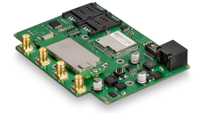
SMT and THT assembly combines surface-mount placement with through-hole connectors, terminals, relays, transformers or press-fit parts on the same PCBA. APTPCB plans the build sequence, stencil, reflow, selective or wave solder, hand-add exceptions, inspection and ICT/FCT coverage before release, so mixed-technology boards do not fail at the solder or test gate.
The critical choice is not SMT versus THT; it is which process solders each component without damaging the others.
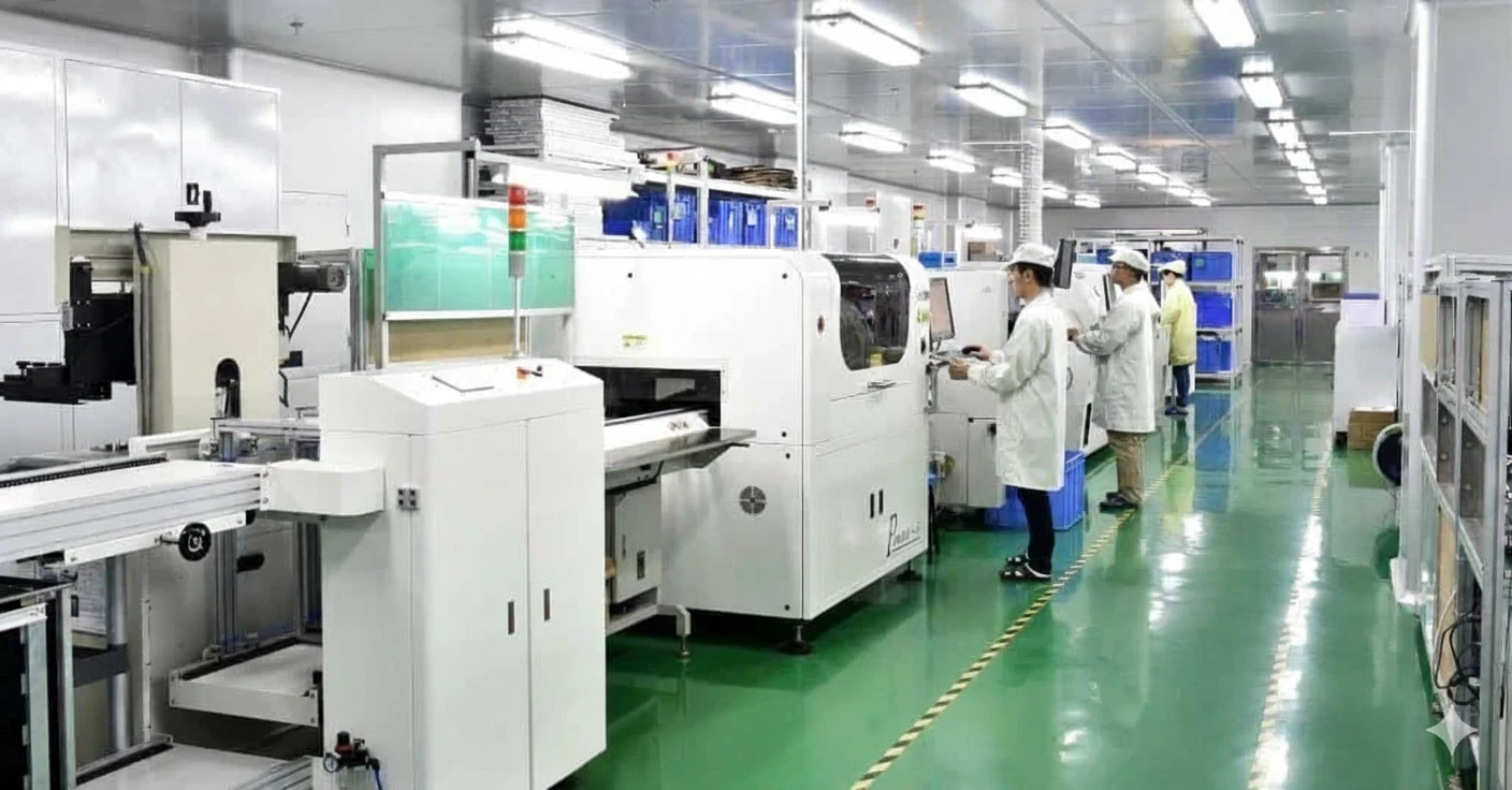
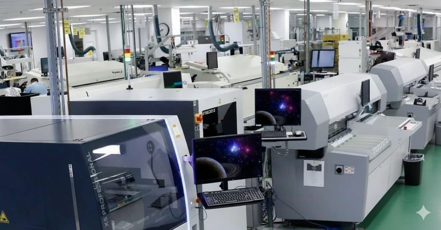
High-speed and flexible lines for paste, placement and reflow before THT insertion.
Fine-pitch passives through odd-form parts planned in one traveler.
Offline kitting and feeder banks keep mixed lots moving.
COVERAGE
A mixed SMT/THT build needs process order, solder access, thermal mass review and test coverage defined before material reaches the line.
Stencil and placement DFM
Area-ratio, aperture, polarity, centroid and fiducial checks reduce print and placement escapes.
SMT reflow control
Nitrogen reflow, thermal profiling and 100% SPI/AOI stabilize fine-pitch and bottom-terminated parts.
THT solder method choice
Selective solder, wave solder, press-fit or controlled manual soldering are chosen by pin access, thermal mass and keep-out risk.
Release evidence
AXI where hidden joints justify it, plus ICT/FCT, boundary-scan and cleanliness records tied to the MES traveler.

PLAYBOOK
The release plan decides process sequence before production, not after the first board shows defects.
DFM and method choice
Review BOM, XY, polarity, tall parts, solder-side keep-outs and decide SMT, selective, wave, press-fit or hand-solder exceptions.
Stencil and SMT setup
Lock stencil design, paste, feeders, placement recipe, reflow profile and first-article inspection.
SMT reflow release
Run 3D SPI, AOI and targeted AXI checks before through-hole insertion blocks access.
THT insertion and solder
Control insertion, pallet/nozzle access, flux, preheat, solder temperature, dwell time and post-solder inspection.
Electrical and shipment release
Run flying probe, ICT, FCT or boundary-scan as required, then ship with inspection and test evidence.
PORTFOLIO
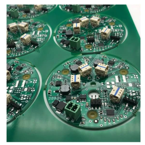
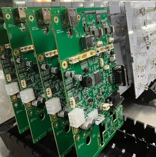
Builds spanning automotive control, medical diagnostics, industrial drives, and compute hardware.
CAPABILITIES
The useful capability is the controlled route from SMT through THT soldering and test, not a standalone placement number.
ESD, humidity, nitrogen and MES travelers control materials from kitting through SMT, THT, test and packing.
QUALITY
Release gates cover paste, reflow, THT soldering, cleanliness and electrical test instead of treating mixed assembly as one generic operation.
SMT reflow is released before THT insertion when later access to BGAs, QFNs or bottom-terminated components will be limited.
Selective, wave, press-fit or manual soldering is chosen by nozzle access, pin count, thermal mass and nearby SMT risk.
A clean RFQ shortens planning: BOM, AVL, XY, assembly drawing, test intent and solder/cleaning constraints.
ECU/inverter boards with selective solder, hi-pot, and PPAP-ready QA.
ISO 13485 builds with cleanliness reports and traceable solder recipes.
Rugged controllers with press-fit, conformal coat, and vibration test.
High-layer, high-power boards with thermal interface prep and RF calibration.
QUALITY & COST
Shared tooling, SPC, and modular fixtures
Quality
Quality
Cost
Cost
Everything you need to know about HDI PCB technology
Upload your files to receive a process route, solder method choice and inspection/test coverage plan.