Inspection of fine-line circuitry for advanced PCB manufacturing

Architecture Before Capability

Advanced PCB Manufacturing Built Around DFM Release

Advanced PCB manufacturing is the controlled fabrication of boards whose interconnect density, material system, thermal path, or mechanical construction exceeds conventional multilayer design rules. APTPCB helps engineering and procurement teams select the least-complex viable architecture, confirm design-specific capability, and define the evidence required before prototype or production release.

Type I–III
HDI Route Selection
DFM Gates
Before Fabrication Release
Build Evidence
Defined in the RFQ

Get an Instant Quote

IPC-2226HDI Design Reference
IPC-6016HDI Performance Reference
Stack-upMaterial & Via Review
VIPPOFill & Cap Definition
ImpedanceCoupon Plan by Order
MicrosectionAcceptance by Requirement
TraceabilityRecords Defined Upfront
NPI to VolumeRelease Rules Preserved
IPC-2226HDI Design Reference
IPC-6016HDI Performance Reference
Stack-upMaterial & Via Review
VIPPOFill & Cap Definition
ImpedanceCoupon Plan by Order
MicrosectionAcceptance by Requirement
TraceabilityRecords Defined Upfront
NPI to VolumeRelease Rules Preserved

A Procurement Decision Page

When Does a PCB Need an Advanced Manufacturing Route?

A board needs an advanced route when conventional plated through-holes, standard multilayer registration, ordinary laminate construction, or a simple thermal-via pattern cannot meet the electrical, mechanical, or packaging requirement. Typical triggers include fine-pitch BGA escape, blind or buried interconnects, repeated sequential lamination, controlled via stubs, rigid-flex transitions, mixed material systems, high copper weight, or a direct thermal path.

The correct response is not to combine every premium process. It is to choose the simplest architecture that meets the design intent and can be repeated at the intended volume. Start with the package map, stack-up, via structure, material class, impedance table, thermal boundary, and qualification requirement. APTPCB reviews those inputs against the proposed route and documents exceptions before tooling. For HDI-specific detail, compare the architecture here with our HDI PCB manufacturing guide.

PCB cross-section comparing conventional multilayer and HDI build-up architectures

Architecture Selection Matrix

Conventional Multilayer vs Type I, II, III and Any-Layer HDI

Choose by routing need and release risk, not by the most aggressive capability on a supplier table. Final geometry, material, layer count, copper weight, and test requirements remain subject to design-specific DFM review.

Manufacturing RouteChoose It WhenRequired Design InputsMain Cost or Reliability Driver
Conventional multilayerMechanical through-holes and standard fan-out satisfy routing, thickness, and signal needs.Layer stack, finished thickness, drill table, copper weights, impedance needs.Layer count, material class, drill aspect ratio, controlled depth features.
IPC-2226 Type I HDIOne build-up layer and blind microvias solve outer-layer escape without buried vias in the core.Microvia span, capture pads, dielectric thickness, laser-drill data, copper-fill requirement.One sequential build-up cycle and registration between the outer layer and core.
IPC-2226 Type II HDIBlind microvias plus buried vias are needed, but routing does not justify multiple microvia layers.Buried-via core construction, press sequence, via fill/cap notes, test access.Additional drilling, plating, lamination, and inspection of the buried structure.
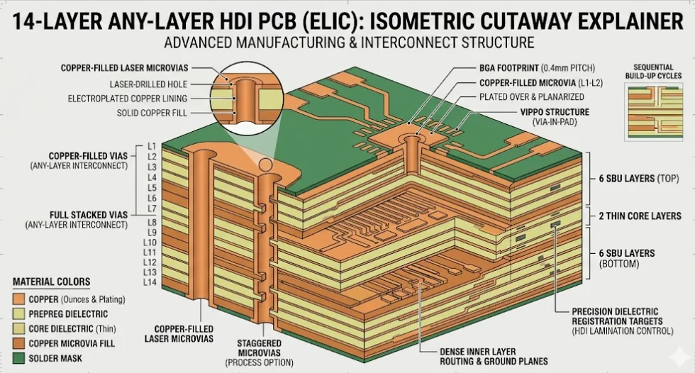
IPC-2226 Type III HDITwo or more microvia layers are required for fine-pitch fan-out or routing density.Complete lamination sequence, stacked or staggered via map, material and copper balance.Each additional cycle adds registration, thermal-history, fill, and yield risk.
Any-layer HDILaser-formed interconnects between many or all layer pairs are essential to the routing architecture.Layer-by-layer interconnect map, pad geometry, via stack, reliability plan, volume target.Repeated build-up, stacked-microvia reliability, dimensional control, and qualification evidence.
Specialized hybrid routeRigid-flex, mixed RF/FR-4 materials, heavy copper, cavities, or copper coins solve a separate mechanical, RF, power, or thermal requirement.Mechanical drawing, bend or thermal model, material callouts, copper profile, assembly interface.Material compatibility, resin flow, copper balance, machining, and process-specific inspection.

Release rule: if a simpler structure meets the package, signal, thermal, and reliability requirements, use it. Do not specify stacked microvias, extra lamination cycles, tight impedance tolerance, or specialty materials without a measurable design reason.

Four Release Gates

What Must Be Agreed Before Advanced PCB Tooling?

A capability statement is not a production release. These four gates convert design intent into an auditable fabrication package.

01

Architecture and Stack-up Gate

Freeze the layer count, material family, dielectric targets, copper weights, via spans, lamination sequence, finished thickness, and surface finish. Record which features are standard for the proposed factory route and which require exception approval.

02

Geometry and Process Gate

Review trace/space by copper weight, annular features, microvia depth-to-diameter relationship, stacked versus staggered construction, VIPPO fill and cap, backdrill depth, rigid-flex transition rules, and panel constraints. Capability is confirmed on the combined design, not one isolated number.

03

Electrical and Reliability Gate

Define impedance targets and tolerance, coupon structure, electrical test coverage, microsection locations, thermal stress or cycling needs, ionic cleanliness where applicable, and the acceptance standard. The test plan must represent the released stack-up.

04

Documentation and Change Gate

Agree the certificate of conformance, material declarations, lot traceability, inspection records, first-article evidence, deviation approval, and change-notification rules required by the purchase order. Verify any quality-system certificate against the legal entity, site, and scope before supplier approval.

Use-Case Fit

Match the Advanced Process to the Constraint

The application name does not select the process. Package density, channel budget, current path, thermal resistance, motion, environment, and compliance responsibility do.

Fine-Pitch Packaging

Dense BGA Escape

Use HDI only where the package map cannot escape through conventional vias. Confirm BGA pitch, pad size, via-in-pad need, microvia spans, assembly land flatness, and inspection access before selecting Type I, II, III, or any-layer construction.

High-Speed Digital

Channels Limited by Loss or Via Stubs

Control the laminate set, pressed dielectric targets, copper profile, reference planes, impedance coupons, and backdrill or blind-via strategy. Protocol name alone does not prove a stack-up will meet the channel budget. See high-speed PCB manufacturing.

Mechanical Integration

Rigid-Flex and Constrained Enclosures

Define static versus dynamic flex use, bend direction and radius, copper type, coverlay, stiffeners, transition keep-outs, and assembly handling. System-level bend life remains dependent on the released design and use profile.

Power and Thermal

Heavy Copper, Cavities and Copper Coins

Start from current, temperature rise, isolation, component junction limits, interface resistance, and cooling method. Thick copper changes etch clearance and resin fill; a copper coin requires a defined mechanical and thermal interface.

RF and Mixed Materials

Hybrid Laminate Construction

Specify the exact laminate, copper, bondply or prepreg, surface finish, RF geometry, and environmental requirement. Hybrid stack-ups require compatibility review for lamination, movement, drilling, desmear, plating, and assembly.

Regulated Programs

Evidence and Responsibility Boundaries

The RFQ must state the product class, customer specification, traceability, inspection, record-retention, and change-control needs. PCB fabrication evidence supports the customer qualification package; final device compliance, safety, and regulatory approval remain the legal manufacturer's responsibility.

Engineering and Procurement Guide

How to Release an Advanced PCB Without Buying Unnecessary Complexity

The strongest RFQ connects every premium process to a requirement and every requirement to acceptance evidence. Use the following sequence before requesting price or lead time.

1. Start with a complete, internally consistent data package

Provide ODB++ or IPC-2581 when available, or Gerber plus NC drill files, together with the netlist, fabrication drawing, stack-up, drill and via table, impedance table, material and finish requirements, panel constraints, applicable standards, quantities, and revision identifier. Separate mechanical, laser, buried, and backdrill data clearly. Conflicting notes and data must be resolved before release.

2. Minimize sequential lamination before optimizing individual dimensions

Each build-up cycle adds thermal exposure, registration work, plating steps, inspection, cost, and yield risk. First test whether a larger package pitch, different fan-out, fewer microvia layers, staggered rather than stacked microvias, or selective HDI can satisfy the routing need. Any-layer construction is justified when the interconnect map requires it—not because it sounds more advanced.

3. Treat microvias and VIPPO as controlled structures

Define the microvia span, target and capture geometry, dielectric thickness, copper fill, stacking, and acceptance method. For via-in-pad, specify whether the via is filled and capped, the finished land requirements, and the applicable IPC-4761 protection type where used. Do not use ‘100% void-free’ or a universal via dimension as a purchasing requirement without an agreed test method and acceptance threshold.

4. Tie impedance to the released material and coupon

The impedance table should identify the layer, single-ended or differential target, reference plane, line width and spacing constraints, and tolerance. The manufacturer then proposes a stack-up using realistic pressed dielectric thickness, copper thickness, and material data. If verification is required, define the coupon design, measurement method, reporting, and disposition rules in the order.

5. Define evidence before the first article is built

Typical evidence may include electrical-test results, impedance reports, microsections, hole or copper measurements, material and finish records, first-article inspection, dimensional reports, and a certificate of conformance. Select only what the product risk and customer specification require. Relevant references can include IPC-2226 for HDI design, IPC-6016 for HDI qualification and performance, IPC-6012 for rigid boards, IPC-6013 for flexible and rigid-flex boards, IPC-4761 for via protection, and IPC-TM-650 test methods. The purchase order must state the required revision and class.

6. Send a quote-ready RFQ package

Include: design data (fabrication files, netlist, drawings, revision); construction (stack-up, materials, copper, via structure, thickness, finish); performance (impedance, current, thermal, mechanical, environmental requirements); quality (class, tests, reports, traceability, change control); and commercial inputs (prototype and volume quantities, panel or delivery preference, target schedule, assembly scope). A complete package produces a more meaningful DFM response and quotation.

Buyer Questions

Advanced PCB Manufacturing FAQ

What makes a PCB manufacturing project advanced?
A project becomes advanced when its density, material system, electrical performance, thermal path, mechanical construction, or evidence requirements exceed a conventional multilayer route. Examples include HDI build-up, blind or buried vias, VIPPO, rigid-flex, mixed RF materials, heavy copper, controlled-depth drilling, cavities, or copper coins. The combined design must be reviewed; one feature alone does not define manufacturability.
How do I choose between Type I, Type II, Type III and any-layer HDI?
Choose the lowest-complexity structure that completes the fan-out and routing. Type I uses one microvia layer without buried vias in the core; Type II adds buried vias; Type III uses two or more microvia layers; any-layer uses laser-formed interconnects across many or all layer pairs. Package map, layer count, via spans, reliability needs, volume, and cost should drive the decision.
Are stacked microvias always better than staggered microvias?
No. Stacked microvias save routing space but add copper-fill, alignment, and reliability demands. Staggered microvias often reduce risk when the layout has room. The preferred structure depends on the via map, dielectric thickness, lamination sequence, thermal exposure, and qualification plan.
When is VIPPO required?
Via-in-pad plated over is useful when a component land must also contain a via, commonly for dense BGA escape or a short thermal or electrical path. The RFQ should define via fill, cap, finished pad flatness, surface finish, and inspection requirements. A conventional dog-bone fan-out is usually simpler when package geometry allows it.
What information is required for an advanced PCB quote?
Send fabrication data, drill files, netlist, fabrication drawing, stack-up, materials, copper weights, via and backdrill definitions, impedance table, finish, finished thickness, applicable standards and class, test and report requirements, quantities, revision, target schedule, and assembly scope. Include bend, thermal, mechanical, or controlled-environment requirements where relevant.
What usually drives advanced PCB cost?
The main drivers are material class, layer count, sequential lamination cycles, stacked microvias, fine geometry, copper weight, rigid-flex construction, hybrid materials, controlled-depth features, surface finish, panel utilization, inspection, qualification evidence, and order quantity. Removing an unnecessary process step usually saves more than negotiating an isolated unit price.
How should microvia and controlled-impedance quality be verified?
Define the evidence in the purchase order. Depending on risk, this may include representative microsections, thermal stress or cycling, electrical test, impedance coupons and reports, copper measurements, material records, and first-article inspection. Acceptance criteria must reference the released stack-up, design data, customer specification, and applicable IPC document revision.
Can an advanced PCB be released directly from prototype to volume?
Only after confirming that the volume route preserves the approved stack-up, materials, design rules, tooling assumptions, test coverage, and evidence package. A prototype made with exceptional handling or a different factory route may not represent volume capability. Treat process transfer and material substitution as controlled changes.
Can APTPCB support medical, automotive, aerospace, or other regulated programs?
APTPCB can review PCB fabrication and documentation requirements for regulated or high-reliability programs. Before approval, verify the current quality-system certificate, legal entity, manufacturing site, scope, applicable standards, records, and any customer-specific requirements for the proposed route. Final product compliance, validation, safety, and regulatory approval remain the customer's responsibility.
How are exact capability limits confirmed?
Exact limits are confirmed from the complete design, not a generic table. Send the stack-up, copper weights, materials, via map, smallest geometry, impedance needs, board size, thickness, finish, test requirements, quantities, and intended factory route. APTPCB will identify standard features, exceptions, trade-offs, and required evidence during DFM review.

Global Program Support

One Release Package for Distributed Engineering Teams

English-language DFM findings, revision-controlled files, and agreed inspection records help engineering, procurement, quality, and manufacturing teams evaluate the same released design across regions.

North America
Engineering and Supplier Qualification

Submit the customer specification, product class, export or security constraints, required records, and approved manufacturing route with the RFQ. Regulatory or contractual eligibility must be confirmed before award.

DFM RecordTraceabilityChange Control
Europe
Material and Compliance Inputs

State material declarations, restricted-substance, quality-system, traceability, language, and document-retention needs explicitly. Do not assume a generic certificate covers every legal entity, site, or process.

Material DataScope CheckRecords
Asia-Pacific
NPI and Volume Transfer

Use one controlled stack-up, design-rule set, approved material list, inspection plan, and deviation process when moving from prototype to production. Differences must be reviewed before the volume release.

NPIVolume RouteDeviation Review
Cross-Region Teams
Revision and Evidence Alignment

Identify the controlling drawing, data revision, purchase specification, acceptance criteria, report format, and approval contacts so commercial and engineering decisions remain tied to the same build definition.

RevisionAcceptanceOwnership

Request a Design-Specific Advanced PCB Review

Upload the fabrication package, stack-up, via map, impedance table, special-process notes, quality requirements, quantities, and target schedule. We will review the proposed route, flag exceptions, and prepare a scope-based quotation.

Contact PCB Engineering