automotive-grade MPPT controller board: what this playbook covers (and who it’s for)
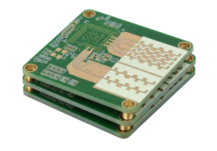
This guide is for electrical engineers, procurement managers, and product leads developing power electronics for the automotive sector. Specifically, it addresses the sourcing and manufacturing of the automotive-grade MPPT controller board. This component is critical for solar-integrated vehicles, recreational vehicles (RVs), and auxiliary EV power systems. It manages energy conversion efficiency while withstanding the harsh realities of the road.
You will not find generic definitions here. Instead, this playbook focuses on the "how-to" of procurement and validation. We cover the specific material requirements that separate automotive boards from standard industrial ones. We detail the hidden risks in scaling up production, such as thermal mismatch and vibration fatigue. Finally, we provide a copy-paste checklist to audit your PCB supplier effectively.
At APTPCB (APTPCB PCB Factory), we understand that an MPPT failure in a vehicle is not just a service call; it is a safety and brand reputation issue. This guide helps you define specifications that prevent failures before they happen. It bridges the gap between your design files and the factory floor.
When automotive-grade MPPT controller board is the right approach (and when it isn’t)
Understanding the operational environment is the first step in selecting the right PCB technology. The automotive-grade MPPT controller board is a specialized solution designed for specific challenges.
Use this approach when:
- Vibration is constant: The device is mounted directly to a vehicle chassis or engine bay where G-forces are significant.
- Temperature swings are extreme: The board must operate reliably from -40°C (winter start) to +105°C or +125°C (under-hood or enclosed operation).
- Lifespan is critical: The product warranty extends beyond 5-10 years, requiring materials that resist aging and delamination.
- Safety standards apply: The system interacts with the main vehicle battery or high-voltage bus, requiring adherence to ISO 26262 or IATF 16949 standards.
- Power density is high: You are pushing high currents (30A+) in a small footprint, similar to an automotive-grade 48V VRM board.
Do not use this approach when:
- The application is stationary: If the MPPT is for a standalone garage solar setup, standard industrial PCBs are sufficient and more cost-effective.
- Cost is the only driver: Automotive-grade materials (High Tg, heavy copper) carry a premium. If the budget is tight and the environment is benign (e.g., inside a climate-controlled cabin with no vibration), a standard FR4 board may suffice.
- Prototype-only phase: For initial functional testing on a bench, standard specs are acceptable. However, move to automotive specs immediately for Design Validation Testing (DVT).
Specs & requirements (before quoting)
To get an accurate quote and a reliable product, you must move beyond basic Gerber files. You need to specify the "unspoken" requirements that ensure automotive reliability.
- Base Material (Laminate):
- Specify High Tg (Glass Transition Temperature) FR4, typically Tg ≥ 170°C.
- Require "automotive-grade" resin systems that are resistant to CAF (Conductive Anodic Filament) growth.
- Examples: Isola 370HR, Panasonic R-1566, or equivalent.
- Copper Weight:
- Define inner and outer layer copper weight explicitly.
- For power paths, 2oz, 3oz, or even 4oz copper is common to manage heat and resistance.
- Specify "finished copper weight" to avoid ambiguity after plating.
- Thermal Management:
- If using a Metal Core PCB (MCPCB), specify the dielectric thermal conductivity (e.g., 2W/mK or 3W/mK).
- If using FR4, define thermal via structures (filled and capped) to transfer heat from FETs to the bottom layer.
- Surface Finish:
- Immersion Silver or ENIG (Electroless Nickel Immersion Gold) is preferred for flat pads and reliable wire bonding.
- Avoid HASL (Hot Air Solder Leveling) for fine-pitch components due to uneven surfaces.
- Solder Mask:
- Specify high-reliability solder mask inks capable of withstanding thermal cycling without cracking.
- Color: Green is standard, but Matte Black is often used for thermal emissivity (though it makes inspection harder).
- Cleanliness Standards:
- Define ionic contamination limits (e.g., < 1.56 µg/cm² NaCl equivalent) per IPC-6012 Class 3.
- Residues can cause electrochemical migration under high voltage.
- Dimensional Stability:
- Tolerances for mounting holes and outline must be tighter than standard (e.g., ±0.10mm) to ensure fitment in vibration-proof enclosures.
- Traceability:
- Require laser marking of QR codes or serial numbers on the PCB waste strip or the board itself for lot tracking.
- Impedance Control:
- If the MPPT includes communication buses (CAN, LIN), specify impedance targets (e.g., 60Ω or 120Ω ±10%).
- Plating Quality:
- Specify minimum copper plating thickness in holes (e.g., average 25µm, min 20µm) to prevent barrel cracks during thermal expansion.
- Bow and Twist:
- Stricter requirement: ≤ 0.5% or 0.75% (standard is often 1.0%) to ensure proper SMT assembly of large power components.
- Automotive Standards:
- Explicitly state "Compliance with IPC-6012 Class 3" on the fabrication drawing.
Hidden risks (root causes & prevention)
Moving from a prototype to mass production introduces risks that are not visible in the design software. These risks often manifest as field failures in automotive-grade MPPT controller board deployments.
- Conductive Anodic Filament (CAF) Growth:
- Risk: High voltage gradients between tracks combined with humidity cause copper filaments to grow along glass fibers, causing shorts.
- Detection: Temperature-Humidity-Bias (THB) testing.
- Prevention: Use CAF-resistant materials and maintain sufficient clearance between high-voltage nets.
- Thermal Expansion Mismatch (CTE):
- Risk: The PCB expands faster than the ceramic components (MLCCs) or large inductors during heating, cracking solder joints.
- Detection: Thermal cycling (-40°C to +125°C).
- Prevention: Use materials with lower z-axis CTE; place stress-relief slots near large components.
- Heavy Copper Etching Undercut:
- Risk: When etching thick copper (3oz+), the chemical eats sideways, reducing the effective trace width and current capacity.
- Detection: Cross-section analysis (microsection).
- Prevention: Apply compensation factors in CAM engineering; increase design trace width spacing.
- Vibration-Induced Fatigue:
- Risk: Heavy inductors and capacitors loosen or crack traces due to vehicle vibration.
- Detection: Vibration tables (random and sine sweep).
- Prevention: Use bonding adhesives (staking) for heavy parts; add extra vias in pads for mechanical strength.
- Potting Compound Stress:
- Risk: Potting material shrinks during cure, pulling components off the board or warping the PCB.
- Detection: Post-potting functional test and X-ray.
- Prevention: Match the CTE of the potting compound to the PCB; use a compliant buffer layer if necessary.
- Solder Voiding in Thermal Pads:
- Risk: Large thermal pads under MOSFETs trap gas, reducing heat transfer and causing overheating.
- Detection: X-ray inspection (aim for < 25% voiding).
- Prevention: Use window-pane stencil designs to allow gas escape.
- Component Counterfeits:
- Risk: Fake power FETs or controllers fail under load.
- Detection: Decapsulation, X-ray, electrical curve tracing.
- Prevention: Source only from authorized distributors; require CoC (Certificate of Conformance).
- Electrochemical Migration:
- Risk: Flux residues + moisture + voltage = dendrite growth.
- Detection: Surface Insulation Resistance (SIR) testing.
- Prevention: rigorous wash processes; use "No-Clean" flux with caution and validation.
- Via Cracking:
- Risk: Z-axis expansion breaks the copper barrel in vias.
- Detection: Interconnect Stress Test (IST).
- Prevention: Ensure plating thickness meets Class 3 (min 25µm average).
- Design for Manufacturing (DFM) Ignorance:
- Risk: Layout works in simulation but is impossible to etch or drill reliably.
- Detection: Early DFM review by the supplier.
- Prevention: Involve the PCB vendor before the layout is frozen.
Validation plan (what to test, when, and what “pass” means)

A robust validation plan is the only way to prove your automotive-grade MPPT controller board is road-ready. This plan should be executed during the EVT (Engineering Validation Test) and DVT (Design Validation Test) phases.
- Electrical Functionality (Room Temp):
- Objective: Verify basic operation.
- Method: Full functional test bench.
- Pass: All voltages/currents within ±1% of spec.
- Thermal Cycling (Shock):
- Objective: Stress solder joints and vias.
- Method: -40°C to +125°C, 15-minute dwell, 500-1000 cycles.
- Pass: No cracks, resistance change < 10%.
- Vibration and Shock:
- Objective: Simulate road conditions.
- Method: ISO 16750-3 random vibration profiles (e.g., engine mount profile).
- Pass: No mechanical detachment, no intermittent electrical contact.
- Humidity / Bias (THB):
- Objective: Check for CAF and migration.
- Method: 85°C / 85% RH with bias voltage applied for 1000 hours.
- Pass: Insulation resistance remains > 100 MΩ.
- High Temperature Operating Life (HTOL):
- Objective: Accelerated aging.
- Method: Run at max power at max ambient temp (e.g., 105°C) for 1000 hours.
- Pass: Efficiency drop < 1%, no component failure.
- Short Circuit Protection:
- Objective: Safety verification.
- Method: Hard short on output while running at full load.
- Pass: System shuts down safely; recovers after reset (or fuse blows safely).
- EMC/EMI Testing:
- Objective: Ensure no interference with vehicle radio/electronics.
- Method: CISPR 25 Class 3 or Class 5 radiated/conducted emissions.
- Pass: Emissions below limit lines.
- Microsection Analysis:
- Objective: Verify PCB build quality.
- Method: Cross-section of vias and traces after thermal stress.
- Pass: Plating thickness ok, no cracks, no delamination.
- Solderability Test:
- Objective: Ensure pads wet properly.
- Method: Dip and look / wetting balance.
- Pass: > 95% coverage.
- Ionic Contamination Test:
- Objective: Cleanliness check.
- Method: ROSE test or Ion Chromatography.
- Pass: < 1.56 µg/cm² NaCl equivalent.
Supplier checklist (RFQ + audit questions)
Use this checklist to vet potential partners. A supplier who cannot answer these clearly is a risk to your project.
RFQ Inputs (What you send)
- Gerber Files (RS-274X): Complete layers including drill, solder mask, and paste.
- Fabrication Drawing: Specifying IPC Class 3, material type (Tg, halogen-free status), and tolerances.
- Stackup Diagram: Defining layer order, copper weights, and dielectric thickness.
- Drill Chart: Defining hole sizes, plating status, and tolerances.
- Panelization Requirements: If you need rails, fiducials, or specific array sizes for your SMT line.
- Volume Estimates: EAU (Estimated Annual Usage) and batch sizes.
- Special Processes: E.g., edge plating, filled vias, controlled depth drilling.
- Testing Requirements: Specific electrical test voltages or TDR requirements.
Capability Proof (What they provide)
- IATF 16949 Certificate: Is it current? Does the scope cover PCB manufacturing?
- Material Datasheets: Can they provide the exact datasheet for the laminate proposed (e.g., Isola/Panasonic)?
- Heavy Copper Capability: Can they etch 3oz/4oz copper with fine lines (e.g., 8mil/8mil)?
- Thermal Management: Do they have experience with metal core or coin insertion if needed?
- Similar Projects: Have they produced an automotive-grade On-board charger PCB or automotive-grade BMS balancing board before?
- Equipment List: Do they have Laser Direct Imaging (LDI) for tight registration?
- Solder Mask Registration: What is their tolerance (typically ±50µm or better)?
- Aspect Ratio: Can they plate high aspect ratio vias (e.g., 10:1) reliably?
Quality System & Traceability
- AOI (Automated Optical Inspection): Is it used on every inner layer?
- E-Test: Do they perform 100% net list testing (flying probe or fixture)?
- Cross-Sectioning: Do they perform microsections on every production panel coupon?
- Traceability: Can they trace a specific board back to the raw material lot and chemical bath data?
- Control Plan: Do they have a specific Control Plan for automotive products?
- MRB (Material Review Board): What is their process for non-conforming material?
- Calibration: Are their measurement tools calibrated to ISO 17025 standards?
Change Control & Delivery
- PCN (Product Change Notification): Do they agree to notify you 6 months in advance of any material or process change?
- Buffer Stock: Are they willing to hold finished goods inventory (VMI) to mitigate supply chain shocks?
- Lead Time: Is the lead time stable? What is the expedite capability?
- Packaging: Do they use moisture barrier bags (MBB) with HIC (Humidity Indicator Cards) and desiccant?
- Logistics: Do they have experience shipping DDP (Delivered Duty Paid) to your location?
- Disaster Recovery: Do they have a backup facility in case of fire or shutdown?
Decision guidance (trade-offs you can actually choose)
Engineering is the art of compromise. Here are the trade-offs specific to automotive-grade MPPT controller board design.
- Heavy Copper vs. Busbars:
- If you prioritize integration: Choose Heavy Copper (3-4oz). It keeps everything on one board but costs more and limits fine-pitch components.
- If you prioritize cost/current: Choose Busbars. Solder external copper bars for high current paths. It’s cheaper for the PCB but adds assembly labor.
- Metal Core (IMS) vs. FR4 with Thermal Vias:
- If you prioritize heat dissipation: Choose Metal Core. Best for single-layer power stages.
- If you prioritize complexity: Choose FR4 with Thermal Vias. Allows multi-layer routing and complex logic control on the same board.
- ENIG vs. HASL:
- If you prioritize reliability/flatness: Choose ENIG. Essential for fine-pitch chips and wire bonding.
- If you prioritize cost: Choose HASL. Only acceptable if components are large and the environment is less corrosive. (Not recommended for automotive).
- Class 2 vs. Class 3:
- If you prioritize safety/longevity: Choose IPC Class 3. Mandatory for critical automotive systems.
- If you prioritize prototype speed: Choose IPC Class 2. Acceptable for initial bench testing only.
- Integrated vs. Modular:
- If you prioritize compactness: Integrate the MPPT with the automotive-grade BMS balancing board. Saves space but increases thermal density.
- If you prioritize serviceability: Keep the MPPT as a separate module. Easier to replace and manage heat.
- High Tg FR4 vs. Standard FR4:
- If you prioritize thermal cycling: Choose High Tg (170°C+). Prevents barrel cracks and pad lifting.
- If you prioritize cost: Standard Tg (130-140°C) is risky for automotive under-hood applications. Avoid it.
FAQ
Q: Can I use standard FR4 for an automotive MPPT? A: Generally, no. Standard FR4 has a lower Tg and lower CAF resistance. For automotive reliability, especially under the hood or in direct sunlight, High Tg material is required to prevent delamination.
Q: What is the difference between an MPPT board and an automotive-grade Digital VRM controller PCB? A: Both manage power, but an MPPT handles variable input from solar panels and focuses on tracking efficiency algorithms. A VRM (Voltage Regulator Module) typically steps down stable DC voltages for processors. However, they share similar requirements for thermal management and signal integrity.
Q: Why is heavy copper expensive? A: It requires more raw material (copper), longer etching times, and more complex lamination processes to fill the gaps between thick traces with resin (prepreg).
Q: Do I need conformal coating? A: Yes. Automotive environments introduce moisture, dust, and chemicals. Conformal coating (acrylic, silicone, or urethane) is essential to prevent corrosion and shorts.
Q: How does an automotive-grade Beamforming module board relate to MPPT? A: While beamforming is for RF/Radar, the advanced substrate sourcing and precise etching required for beamforming boards are similar to the quality levels needed for high-efficiency MPPT power stages using GaN or SiC switches.
Q: What is the biggest cause of failure in these boards? A: Thermal fatigue. The constant heating (from power conversion) and cooling (when the vehicle stops) causes expansion and contraction that eventually cracks solder joints or vias.
Q: Can APTPCB help with the layout? A: We specialize in DFM (Design for Manufacturing). While we don't design the circuit logic, we optimize the layout for production yield, thermal performance, and cost reduction.
Q: What is the typical lead time for automotive prototypes? A: With standard materials, 5-7 days. For specialized automotive laminates or heavy copper, allow 10-15 days to ensure proper pressing and curing cycles.
Related pages & tools
- Automotive Electronics PCB – Understand the broader context of automotive quality standards and capabilities.
- Heavy Copper PCB – Deep dive into the manufacturing constraints and benefits of thick copper for high-current MPPTs.
- High Tg PCB – Learn why glass transition temperature matters for reliability in harsh thermal environments.
- DFM Guidelines – Essential design rules to ensure your board can be manufactured without delays.
- ICT Test – Details on In-Circuit Testing, a crucial validation step for automotive production.
- Quality System – Review the certifications and quality control processes that protect your supply chain.
Request a quote
Ready to move from design to validation? The APTPCB engineering team provides a comprehensive DFM review to catch thermal and mechanical risks before you commit to tooling.
To get an accurate quote and DFM analysis, please prepare:
- Gerber Files (RS-274X format).
- Stackup & Drill Drawing (PDF).
- Bill of Materials (BOM) if assembly is required.
- Testing Requirements (ICT/FCT specs).
- Estimated Volume (Prototype vs. Mass Production).
Click here to upload your files and request a quote. We typically respond with a technical review within 24 hours.
Conclusion
Sourcing an automotive-grade MPPT controller board is about more than just finding a vendor; it is about establishing a partnership for reliability. By defining strict material requirements, understanding the risks of thermal and mechanical stress, and validating with a rigorous test plan, you ensure your power system survives the road. Whether you are building a solar RV system or an auxiliary EV charger, the right PCB foundation is the difference between a long service life and a field failure.