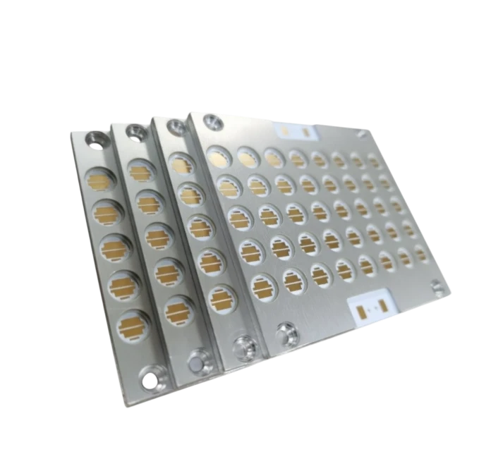
A Brake Light PCB is a specialized printed circuit board designed to drive high-intensity red LED arrays for automotive rear signaling, requiring exceptional thermal management to prevent junction burnout during prolonged braking. Unlike standard consumer electronics, these boards must endure the harsh automotive environment, including voltage transients up to 60V and temperature fluctuations ranging from -40°C to +125°C.
Key Takeaways
- Thermal Management is Critical: High-brightness LEDs generate significant heat; Metal Core PCBs (MCPCB) with thermal conductivity > 2.0 W/mK are the standard.
- Vibration Resistance: Solder joints must withstand random vibration profiles (e.g., 5–2000 Hz) without fatigue cracking.
- Material Selection: FR4 is often insufficient for main brake lights; Aluminum or Copper substrates are preferred for heat dissipation.
- Luminance Consistency: Trace resistance must be balanced to ensure uniform brightness across the entire LED array.
- Regulatory Compliance: Designs must meet ECE/SAE photometric standards, which dictates PCB layout precision.
- Validation Threshold: Passing 1,000 hours of 85°C/85% RH (Temperature/Humidity) testing is a common acceptance criterion.
- Cost vs. Performance: While Metal Core PCBs cost 20–30% more than FR4, they eliminate the need for bulky external heatsinks.
Contents
- What It Really Means (Scope & Boundaries)
- Metrics That Matter (How to Evaluate It)
- How to Choose (Selection Guidance by Scenario)
- Implementation Checkpoints (Design to Manufacturing)
- Common Mistakes (and the Correct Approach)
- FAQ (Cost, Lead Time, Materials, Testing, Acceptance Criteria)
- Glossary (key terms)
- Conclusion (next steps)
What It Really Means (Scope & Boundaries)
A Brake Light PCB is not merely a carrier for LEDs; it is an active thermal management system and a structural component of the vehicle's safety architecture. The scope of this technology extends beyond simple on/off functionality. Modern automotive lighting integrates complex logic for sequential turn signals, adaptive braking intensity, and integration with the vehicle's CAN bus or LIN bus networks.
The boundaries of this technology are defined by the application's power density. A standard Dashboard Light PCB might use low-power SMDs on a standard FR4 board because the thermal load is negligible. However, a Brake Light PCB or a Beacon Light PCB (used in emergency vehicles) operates high-power emitters that can reach junction temperatures of 150°C within seconds if heat is not extracted efficiently.
Furthermore, the form factor is rarely flat. Modern vehicle styling demands 3D contours. This often necessitates Rigid-Flex PCB solutions or specialized flexible substrates that can conform to the curvature of the tail light housing. This contrasts with an Accent Light PCB or Ambient Light PCB, which might use simple flexible LED strips but do not carry the same safety-critical reliability requirements as the primary brake lamp.
Metrics That Matter (How to Evaluate It)
Evaluating a Brake Light PCB requires analyzing both the material properties of the bare board and the electrical performance of the assembly. The following tables outline the critical ranges for a robust design.
Table 1: Thermal and Mechanical Metrics
| Metric | Typical Range / Limit | Why It Matters | How to Verify |
|---|---|---|---|
| Thermal Conductivity | 1.0 – 3.0 W/mK | Determines how fast heat moves from LED to heatsink. Low values lead to LED dimming or failure. | ASTM D5470 or Laser Flash Analysis. |
| Glass Transition (Tg) | > 150°C (High Tg) | Prevents PCB expansion/delamination during reflow and operation in hot climates. | TMA (Thermomechanical Analysis). |
| CTE (Z-axis) | < 50 ppm/°C | Controls expansion stress on plated through-holes (PTH) during thermal cycling. | TMA; check datasheet against IPC-4101. |
| Peel Strength | > 1.0 N/mm | Ensures copper traces do not lift under thermal stress or vibration. | IPC-TM-650 2.4.8 test method. |
| Dielectric Breakdown | > 3.0 kV AC | Prevents arcing between the copper layer and the metal core (for MCPCBs). | Hi-Pot testing during fabrication. |
| Solder Mask Hardness | > 6H Pencil Hardness | Resists scratching during assembly and handling; protects against moisture. | IPC-SM-840 qualification. |
Table 2: Electrical and Optical Performance Metrics
| Metric | Target Threshold | Impact on Function | Common Failure Mode |
|---|---|---|---|
| Voltage Drop | < 3% across array | Ensures uniform brightness from the first LED to the last in the series. | "Dim tail" effect where one side looks weaker. |
| Copper Weight | 2 oz (70 µm) or 3 oz | Reduces resistance for high-current traces; aids lateral heat spreading. | Overheating traces causing delamination. |
| Surface Finish | ENIG or Immersion Silver | Provides flat surface for fine-pitch LED placement and wire bonding. | HASL unevenness causes LED tilting (tombstoning). |
| LED Junction Temp | < 110°C (derated) | Keeps LED within safe operating area to maintain lifespan (L70 > 50k hours). | Thermal camera verification during load test. |
| Leakage Current | < 10 µA | Prevents "ghosting" (faint glow) when the car is off. | High-impedance meter check. |
How to Choose (Selection Guidance by Scenario)
Selecting the right PCB technology depends heavily on the specific lighting function and the mechanical constraints of the housing. Use these decision rules to navigate the trade-offs.
- If the LED power density exceeds 1W/cm², choose an Aluminum Metal Core PCB (MCPCB) to manage the thermal load effectively.
- If the design requires the light to wrap around the vehicle corner (e.g., Cornering Light PCB), choose a Rigid-Flex PCB or a polyimide Flex PCB with stiffeners.
- If cost is the primary driver and LED current is low (< 50mA), choose FR4 with Heavy Copper (2oz+) and thermal vias rather than a full metal core.
- If the application is a high-voltage EV system (> 60V), choose a dielectric layer with high breakdown voltage (> 4kV) to prevent shorting to the chassis.
- If the assembly involves wire bonding for Chip-on-Board (COB) LEDs, choose ENEPIG surface finish for robust wire bondability.
- If the light is an Ambient Light PCB inside the cabin with minimal heat, choose standard FR4 or low-cost CEM-3 materials.
- If the operating environment involves salt spray or high humidity, choose to apply Conformal Coating (silicone or acrylic) post-assembly.
- If the design requires complex logic (microcontrollers) alongside power LEDs, choose a hybrid stack-up or a rigid board with a separate LED daughterboard.
- If the LED color binning is critical, choose white solder mask with high reflectivity (> 85%) to maximize lumen output and color consistency.
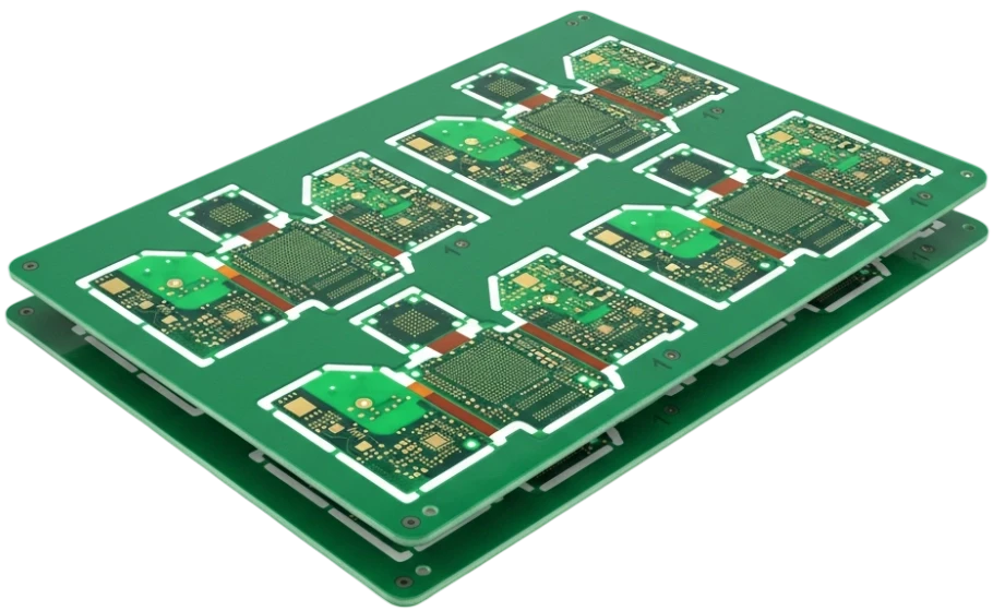
- If the production volume is high and the shape is simple, choose V-scoring for panelization to minimize waste and reduce assembly costs.
Implementation Checkpoints (Design to Manufacturing)
Successful production of a Brake Light PCB requires a disciplined approach from the schematic phase through to final assembly.
Phase 1: Design & Layout
- Thermal Simulation:
- Action: Run a thermal simulation (CFD) assuming worst-case ambient temperature (e.g., 85°C).
- Acceptance: Simulated LED junction temperature must remain 10°C below the manufacturer's maximum rating.
- Current Density Check:
- Action: Calculate trace widths based on IPC-2152 standards for the target current.
- Acceptance: Temperature rise of traces must be < 10°C above ambient at max current.
- Panelization Strategy:
- Action: Design the panel with tooling strips and fiducials for automated assembly.
- Acceptance: Panel utilization > 80% to optimize material costs.
Phase 2: Fabrication (PCB Manufacturing)
- Dielectric Thickness Verification:
- Action: Measure the dielectric layer thickness between copper and metal core (for MCPCB).
- Acceptance: Thickness must be within ±10% of the specified value (typically 75µm to 100µm).
- Solder Mask Adhesion:
- Action: Perform a tape test (IPC-TM-650 2.4.28.1) on the white solder mask.
- Acceptance: No solder mask removal allowed; critical for reflectivity and protection.
- Surface Finish Measurement:
- Action: X-ray fluorescence (XRF) measurement of ENIG/Immersion Silver thickness.
- Acceptance: Gold thickness 2–5 µin; Nickel 120–240 µin (for ENIG).
Phase 3: Assembly (PCBA)
- Solder Paste Inspection (SPI):
- Action: Use 3D SPI to measure paste volume on thermal pads.
- Acceptance: Paste volume 80%–120% of stencil aperture volume.
- Void Analysis (X-Ray):
- Action: X-ray inspection of the thermal pad solder joint under the LED.
- Acceptance: Total voiding area < 25%; largest single void < 10% of pad area.
- Functional Test (FCT):
- Action: Power up the board at nominal voltage and measure current draw.
- Acceptance: Current must be within ±5% of design target; all LEDs illuminate.
- Burn-In Testing:
- Action: Operate the board at max power for 4–8 hours.
- Acceptance: No flickering, color shift, or catastrophic failures.
Common Mistakes (and the Correct Approach)
Even experienced engineers can overlook the nuances of automotive lighting PCBs. Here are the most frequent errors and how to avoid them.
1. Ignoring Thermal Expansion Mismatch
- Mistake: Using a standard FR4 dielectric with large ceramic LEDs without considering CTE (Coefficient of Thermal Expansion).
- Impact: Solder joints crack after a few hundred thermal cycles due to stress.
- Fix: Use a matched CTE substrate or compliant solder alloys.
- Verify: Perform 1000 cycles of -40°C to +125°C thermal shock testing.
2. Insufficient Thermal Vias
- Mistake: Placing thermal vias too far from the LED thermal pad or using too few vias on an FR4 design.
- Impact: High thermal resistance creates hot spots, reducing LED life.
- Fix: Place vias directly in the pad (Via-in-Pad) or immediately adjacent; fill and cap if necessary.
- Verify: Thermal imaging during prototype testing.
3. Wrong Solder Mask Color
- Mistake: Using standard green solder mask for lighting applications.
- Impact: Green absorbs light, reducing overall fixture efficiency and altering color temperature.
- Fix: Always specify "Super White" or high-reflectivity solder mask.
- Verify: Reflectivity measurement (should be > 85%).
4. Overlooking Transient Protection
- Mistake: Designing for 12V DC without protection against load dump (voltage spikes).
- Impact: LEDs or driver ICs burn out when the vehicle alternator spikes.
- Fix: Include TVS diodes and input capacitors rated for automotive transients (ISO 7637).
- Verify: Pulse testing according to automotive standards.
5. Poor Panelization for V-Cut
- Mistake: Placing copper features or components too close to the V-score line on an Aluminum PCB.
- Impact: The scoring blade exposes copper or cracks ceramic capacitors, causing shorts.
- Fix: Maintain a clearance of at least 1.0mm from the V-score line for copper, 2.0mm for components.
- Verify: Gerber review using DFM Guidelines.
6. Inadequate Copper Weight
- Mistake: Using standard 1oz copper for high-current brake light strings.
- Impact: Excessive voltage drop causes the last LED in the string to be dimmer than the first.
- Fix: Use 2oz or 3oz copper, or widen traces significantly.
- Verify: Voltage drop calculation and physical measurement.
7. Neglecting Moisture Protection
- Mistake: Assuming the tail light housing is perfectly sealed.
- Impact: Condensation corrodes traces and causes leakage currents.
- Fix: Apply conformal coating or use potting compounds for critical areas.
- Verify: Salt spray and humidity chamber testing.
8. Underestimating Mechanical Vibration
- Mistake: Placing heavy components (inductors, large caps) without adhesive support.
- Impact: Components shear off the pads due to road vibration.
- Fix: Use adhesive staking for heavy components; verify pad geometry.
- Verify: Vibration testing (random and sine sweep).
FAQ (Cost, Lead Time, Materials, Testing, Acceptance Criteria)
Q: How does the cost of a Metal Core PCB compare to FR4 for brake lights? A: A Metal Core PCB (MCPCB) typically costs 20% to 50% more than a standard FR4 board due to the aluminum material and specialized processing.
- FR4: Lower raw material cost, standard processing.
- MCPCB: Higher material cost, requires specialized routing/scoring tools.
- System Cost: MCPCB often lowers total system cost by removing external heatsinks.
Q: What is the standard lead time for manufacturing Brake Light PCBs? A: Standard lead times are generally 2–3 weeks for production volumes, with quick-turn options available.
- Prototype: 3–5 days (depending on material availability).
- Production: 10–15 working days.
- Note: Specialized materials (e.g., 3oz copper, specific dielectric) may add 1 week.
Q: Can I use FR4 for a Brake Light PCB? A: Yes, but only for low-power designs or if extensive thermal vias and external heatsinking are used.
- Low Power: < 0.5W total dissipation might work on FR4.
- High Power: > 1W usually requires MCPCB.
- Risk: FR4 has poor thermal conductivity (0.3 W/mK) compared to MCPCB (2.0+ W/mK).
Q: What testing is required for automotive lighting PCBs? A: Automotive PCBs must undergo rigorous reliability testing to meet AEC-Q100 and other standards.
- Thermal Shock: -40°C to +125°C (500–1000 cycles).
- Vibration: Random vibration profiles simulating road conditions.
- Burn-in: 100% functional burn-in is often required for safety-critical brake lights.
Q: What is the best surface finish for LED wire bonding? A: ENEPIG (Electroless Nickel Electroless Palladium Immersion Gold) is the gold standard for wire bonding reliability.
- ENIG: Good for soldering, acceptable for some wire bonding.
- ENEPIG: Superior wire bond strength and corrosion resistance.
- Immersion Silver: Good reflectivity but risks tarnishing if not handled correctly.
Q: How do I prevent "tombstoning" of small LED components? A: Tombstoning occurs when wetting forces are unbalanced during reflow.
- Design: Ensure thermal pads are symmetrical and have thermal relief if connected to large planes.
- Process: Optimize reflow profile (soak zone) to equalize temperatures.
- Placement: Ensure accurate placement pressure and position.
Q: What is the difference between a Brake Light PCB and a Beacon Light PCB? A: The primary difference lies in the duty cycle and intensity.
- Brake Light: Intermittent high power, safety-critical, regulated beam pattern.
- Beacon Light: Continuous flashing/strobe, extremely high intensity, often 360-degree coverage.
- Thermal: Beacon lights often require even more aggressive thermal management due to continuous operation.
Q: What are the acceptance criteria for LED solder voids? A: Excessive voids impede heat transfer, leading to early LED failure.
- IPC Standard: IPC-A-610 Class 3 (High Reliability).
- Threshold: Typically < 25% total void area under the thermal pad.
- Critical: No single void should traverse the entire width of the thermal path.
Glossary (Key Terms)
| Term | Definition | Context in Brake Lights |
|---|---|---|
| MCPCB | Metal Core Printed Circuit Board. | A PCB with a metal base (usually Aluminum) for heat dissipation. |
| IMS | Insulated Metal Substrate. | Another name for MCPCB; the dielectric layer is the key insulator. |
| Junction Temperature (Tj) | The internal temperature of the LED chip. | The critical metric to control; exceeding max Tj causes failure. |
| Luminous Flux | The total light output of the LED (measured in Lumens). | Brake lights must meet specific lumen targets for legality. |
| Thermal Conductivity (k) | Measure of a material's ability to conduct heat (W/mK). | Higher 'k' values in the dielectric mean cooler LEDs. |
| Dielectric Breakdown | The voltage at which the insulation layer fails. | Critical for safety, ensuring the metal core doesn't become live. |
| AEC-Q100 | Automotive Electronics Council qualification standard. | The industry benchmark for stress testing active components. |
| PPAP | Production Part Approval Process. | The documentation and validation process required by auto OEMs. |
| CAN Bus | Controller Area Network. | The vehicle network that might trigger the brake light signal. |
| Fiducial Marker | Optical recognition mark on the PCB. | Essential for precise placement of LEDs during assembly. |
| TVS Diode | Transient Voltage Suppressor. | Protects the circuit from high-voltage spikes (load dump). |
| Binning | Sorting LEDs by color and brightness. | Ensures all LEDs on the brake light look identical. |
Conclusion (Next Steps)
Designing and manufacturing a Brake Light PCB is a balance of thermal physics, electrical efficiency, and rigorous mechanical validation. By selecting the correct substrate—typically a high-conductivity Metal Core PCB—and adhering to strict design rules regarding copper weight and thermal vias, you ensure the safety and longevity of the automotive signaling system.