Quick Answer (30 seconds)
A reliable cryogenic compatible SMT process requires managing extreme Coefficient of Thermal Expansion (CTE) mismatches and ensuring material ductility at temperatures near absolute zero (4K or lower).
- Alloy Selection: Standard SAC305 often becomes brittle below 77K. Indium-based alloys or high-lead solders are preferred for their ductility, though specific superconducting requirements may dictate pure Indium or SnPb.
- Flux Management: Flux residues can freeze, crack, or outgas in vacuum cryostats. A flux free soldering quantum PCB process or rigorous cleaning is mandatory.
- Component Screening: Standard commercial components often contain nickel barriers which become magnetic. Use non-magnetic terminations (Ag/Pd) for quantum applications.
- Substrate Matching: Match the CTE of the PCB substrate (e.g., Rogers/Teflon) to the components to prevent solder joint fatigue during thermal cycling.
- Validation: Mandatory thermal shock testing (liquid nitrogen dip) and continuity monitoring during cool-down.
When cryogenic compatible SMT process applies (and when it doesn’t)

Understanding the thermal domain is critical before selecting materials. Cryogenic SMT is distinct from standard industrial "low temperature" electronics.
Applies to:
- Quantum Computing Hardware: Systems operating at dilution refrigerator temperatures (10mK–4K) requiring superconducting interconnects.
- Deep Space Instrumentation: Sensors and control boards exposed to <100K environments without active heating.
- Superconducting Magnet Controls: Electronics embedded within liquid helium or nitrogen baths (MRI, particle accelerators).
- Infrared Focal Plane Arrays: Detectors requiring cryogenic cooling for signal-to-noise ratio performance.
- Low Magnetic Environments: Assemblies requiring low magnetic connector assembly techniques to avoid spin decoherence.
Does NOT apply to:
- Industrial Freezers: Standard -40°C operating ranges can be handled by standard IPC Class 3 automotive specs.
- Consumer Electronics: Outdoor usage rarely drops below -20°C; standard FR4 and SAC305 are sufficient.
- Short-duration High Altitude: Weather balloons often use insulation rather than full cryogenic hardening.
- Standard Aerospace Cabin: Pressurized and heated avionics bays do not require cryogenic solder alloys.
Rules & specifications
The following specifications define the boundaries for a successful cryogenic assembly. APTPCB (APTPCB PCB Factory) uses these parameters to validate designs before production.
| Rule | Recommended Value/Range | Why it matters | How to verify | If ignored |
|---|---|---|---|---|
| Solder Alloy Ductility | Indium (In97Ag3) or Sn63Pb37 | SAC305 undergoes a ductile-to-brittle transition below ~100K. | Shear strength test at LN2 temp. | Solder joints shatter during cool-down; intermittent open circuits. |
| Substrate CTE (Z-axis) | < 30 ppm/°C | High Z-axis expansion rips plated through-holes (PTH) during thermal cycling. | TMA (Thermomechanical Analysis). | Barrel cracks in vias; layer separation. |
| Flux Residue | < 1.5 µg/cm² (or Flux-free) | Residues crack at cryogenic temps or outgas in vacuum, contaminating optics/qubits. | ROSE testing / Ion Chromatography. | Vacuum pump failure; sensor contamination; capacitive noise. |
| Component Terminations | Non-magnetic (Ag/Pd, Cu) | Nickel barriers become ferromagnetic, disturbing quantum states. | Gaussmeter check / SQUID magnetometer. | Qubit decoherence; magnetic field distortion. |
| Voiding Percentage | < 10% (Strict) | Voids act as stress concentrators where cracks initiate under thermal stress. | X-Ray Inspection (2D/3D). | Premature joint failure after few thermal cycles. |
| PCB Surface Finish | ENIG or EPIG (Non-magnetic) | HASL is uneven; Immersion Tin can grow whiskers. ENIG provides flat, conductive pads. | XRF coating thickness measurement. | Poor planarity for fine-pitch parts; potential magnetic interference (if Nickel too thick). |
| Conformal Coating | Parylene C / None | Standard acrylics/silicones may shatter or stress components at 4K. | Visual inspection / Thickness check. | Coating cracks damage underlying components; wire bond lift-off. |
| Minimum Bend Radius | > 10x Cable Diameter | Cables stiffen significantly; tight bends induce stress on connectors. | Visual / Mechanical gauge. | Connector shell cracking; solder pad lift-off. |
| Cooling Rate | < 10 K/min (System dependent) | Rapid cooling induces thermal shock due to thermal mass differences. | Thermocouple profiling. | Ceramic capacitor cracking; BGA warping. |
| Intermetallic Thickness | 1–3 µm | Excessive IMC is brittle and fails faster at low temps. | Cross-section analysis. | Joint embrittlement; reduced fatigue life. |
Implementation steps
Executing a cryogenic compatible SMT process requires modifying the standard assembly flow. Follow these steps to ensure reliability.
Substrate & Material Selection
- Action: Select a substrate with low CTE and high thermal stability.
- Parameter: Prefer Teflon PCB or specialized Rogers laminates over standard FR4.
- Check: Verify Tg (Glass Transition Temperature) is not the primary concern, but rather CTE matching with ceramic components.
Component Magnetic Screening
- Action: Screen BOM for ferromagnetic materials if the application is quantum or sensitive sensing.
- Parameter: Magnetic permeability $\mu_r \approx 1$.
- Check: Use a magnet or susceptibility meter on sample batches of capacitors and resistors.
Stencil Design for Ductility
- Action: Modify aperture design to ensure sufficient solder volume for stress compliance.
- Parameter: 1:1 aperture ratio or slight overprint for compliant leads.
- Check: Inspect solder paste height; ensure volume is sufficient to form a compliant fillet.
Reflow Profiling (Low Peak)
- Action: Adjust reflow profile for the specific alloy (Indium melts at ~156°C, SnPb at 183°C).
- Parameter: Peak temperature 15–20°C above liquidus; minimize time above liquidus (TAL) to limit IMC growth.
- Check: Run a profiler board with thermocouples on the largest thermal mass.
Flux Removal / Plasma Cleaning
- Action: Remove all flux residues immediately after reflow.
- Parameter: Saponifier wash followed by DI water rinse; Plasma clean for wire-bond pads.
- Check: Visual inspection under UV light (if flux is fluorescent) or ionic contamination test.
Cryogenic Verification (Lot Acceptance)
- Action: Perform a "dip test" on a sample coupon from the production lot.
- Parameter: 3 cycles of rapid immersion in Liquid Nitrogen (77K) and return to ambient.
- Check: Micro-sectioning to look for micro-cracks in solder fillets or via barrels.
Low Magnetic Connector Assembly
- Action: Install connectors using non-magnetic hardware and solder.
- Parameter: Use brass or beryllium copper screws instead of steel; verify plating is non-magnetic.
- Check: Verify mechanical torque does not stress the solder joints.
Final Electrical Test at Temperature
- Action: Measure resistance/continuity while the board is cold (if feasible) or immediately after cycling.
- Parameter: Watch for "glitch" opens that disappear at room temperature.
- Check: 4-wire resistance measurement on critical nets.
Failure modes & troubleshooting
Cryogenic failures are often latent, appearing only when the system is cold.
1. Solder Joint Fatigue (Cracking)
- Symptom: Intermittent open circuits at <100K; functional at Room Temp.
- Causes: CTE mismatch between ceramic component (6 ppm/°C) and PCB (14-18 ppm/°C). Solder alloy too brittle (SAC305).
- Checks: Cross-section analysis showing cracks through the bulk solder or IMC interface.
- Fix: Switch to Indium-based alloys or high-lead (Sn10Pb90) if RoHS permits. Use compliant "gull-wing" leads instead of leadless chips.
- Prevention: Run DFM guidelines specifically checking for large ceramic packages on FR4.
2. Ceramic Capacitor Cracking
- Symptom: Short circuit or capacitance drift.
- Causes: Thermal shock during cool-down; board flexing.
- Checks: Acoustic microscopy (CSAM) or visual inspection for hairline cracks.
- Fix: Use "soft termination" capacitors (polymer layer). Orient capacitors parallel to the board's flex axis.
- Prevention: Control cooling rates (<10 K/min).
3. Via Barrel Fracture
- Symptom: Open circuit in internal layers.
- Causes: Z-axis expansion of resin exceeds ductility of copper plating.
- Checks: Resistance change during thermal cycling.
- Fix: Use high-aspect-ratio plating specs (min 25µm copper). Use substrates with lower Z-axis CTE.
- Prevention: Specify IPC Class 3 plating thickness.
4. Flux Outgassing / Contamination
- Symptom: Pressure spikes in vacuum chamber; degradation of optical sensors.
- Causes: Trapped flux volatiles releasing in vacuum.
- Checks: Residual Gas Analysis (RGA) in vacuum chamber.
- Fix: Implement aggressive cleaning or switch to flux free soldering quantum PCB methods (e.g., formic acid reflow).
- Prevention: Validate cleaning process with Ion Chromatography.
5. Superconducting Shorting (Tin Whiskers)
- Symptom: Unexplained shorts in high-density areas.
- Causes: Pure tin plating stresses growing whiskers, which may become superconducting.
- Checks: SEM inspection of lead surfaces.
- Fix: Use SnPb finishes or Ni/Pd/Au. Avoid pure tin.
- Prevention: Prohibit pure tin components in procurement specs.
Design decisions
Successful cryogenic boards start with design choices that differ from standard commercial electronics.
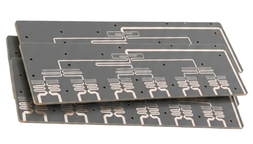
Substrate Selection Standard FR4 is often usable down to 77K but becomes unpredictable at mK temperatures. For deep cryogenic applications, Rogers 4003C or RT/duroid (PTFE based) are preferred due to their consistent dielectric constant and lower CTE. Rogers PCB materials provide better stability for RF signals in quantum processors.
Solder Alloy Strategy
- Indium (In97Ag3): Remains ductile down to absolute zero. It is soft and compliant, absorbing stress. However, it forms brittle intermetallics with gold; gold must be removed from pads before soldering.
- Sn63Pb37: Better than SAC305 but still stiffens. Used where Indium is too soft or expensive, provided the CTE mismatch is managed.
- SAC305 (Lead-Free): Generally avoided for deep cryo due to "tin pest" (allotropic transformation) and brittleness, though some modified alloys exist.
Passive Component Sizing Avoid large case sizes (1206, 1210) for ceramic resistors/capacitors. Smaller packages (0402, 0201) have less surface area to accumulate stress from CTE mismatch. If large values are needed, use leaded components or arrays with compliant terminations.
FAQ
Q: Can I use standard lead-free solder (SAC305) for cryogenic applications? A: It is risky. SAC305 becomes brittle at cryogenic temperatures and is prone to cracking under thermal cycling. For high reliability, Indium alloys or SnPb are recommended.
Q: What is the best surface finish for cryogenic PCBs? A: ENIG (Electroless Nickel Immersion Gold) is common, but for magnetic-sensitive applications (Quantum), OSP or Immersion Silver is preferred to avoid the nickel layer. If wire bonding is required, ENEPIG is a viable option.
Q: How do I specify a flux-free process? A: Specify "Flux-free soldering" in your assembly notes. This typically involves using formic acid vapor reflow or pre-tinned components with plasma cleaning, ensuring no organic residues remain.
Q: Why is magnetic screening important? A: In quantum computing, magnetic fields from nickel barriers in standard resistors can cause qubit decoherence. You must specify "non-magnetic" passives (often constructed with silver/palladium terminations).
Q: Does APTPCB handle Indium soldering? A: Yes, APTPCB supports specialized alloy assembly, including Indium and low-temperature solders. Contact our engineering team for specific DFM checks on Indium processes.
Q: What is the risk of "Tin Pest"? A: Tin pest is the transformation of Beta-tin to Alpha-tin at low temperatures, causing the solder to crumble. Alloys with <0.5% antimony or bismuth inhibit this. Most commercial SAC alloys are susceptible over long durations.
Q: How do connectors behave at 4K? A: Plastic housings shrink and become brittle. Use PEEK or LCP housings. Ensure the low magnetic connector assembly uses non-magnetic shells to prevent field distortion.
Q: Is conformal coating necessary? A: Often no. In a vacuum cryostat, condensation isn't an issue. Coatings can induce stress. If needed for handling protection, use a thin layer of Parylene.
Q: How do I test for cryogenic reliability without a cryostat? A: Liquid Nitrogen (LN2) dip testing is the industry standard proxy. While it only reaches 77K, it stresses the joints significantly enough to reveal most CTE mismatch failures.
Q: What is the lead time for cryogenic SMT assembly? A: It depends on material availability (e.g., specialized solders or non-magnetic parts). Typically, add 1–2 weeks to standard lead times for specialized reflow profiling and validation steps.
Q: Can I use FR4 for 4K applications? A: Yes, but with caveats. FR4 survives 4K, but its thermal contraction is anisotropic. You must design with ample clearances and avoid large ceramic parts directly soldered to it.
Q: What about BGA components in cryo? A: BGAs are challenging. Use interposers or underfill specifically rated for cryo (though rare). Column Grid Arrays (CGA) offer better compliance than balls.
Related pages & tools
- PCB Manufacturing Services: Full-service fabrication for high-reliability boards.
- Rogers PCB Materials: High-frequency laminates suitable for cryogenic thermal stability.
- DFM Guidelines: Design rules to prevent manufacturing defects before they happen.
- Quote Request: Get a cost estimate for your cryogenic assembly project.
Glossary (key terms)
| Term | Definition |
|---|---|
| CTE (Coefficient of Thermal Expansion) | The rate at which a material expands or contracts with temperature changes. Mismatch causes stress. |
| Ductile-to-Brittle Transition | The temperature at which a material loses its ability to deform plastically and becomes prone to shattering. |
| Indium Solder | A soft, ductile solder alloy (often In/Ag or In/Pb) used for cryogenic seals and interconnects. |
| Superconductivity | A state where electrical resistance drops to zero, occurring in certain materials below a critical temperature ($T_c$). |
| Outgassing | The release of trapped gas or vapor from materials (like flux or epoxy) in a vacuum environment. |
| Cryostat | A device used to maintain cryogenic temperatures, often using liquid helium or cryocoolers. |
| Thermal Shock | Structural damage caused by rapid temperature change, creating internal stress. |
| Non-magnetic | Materials with magnetic permeability close to 1, essential for avoiding interference in quantum circuits. |
| Intermetallic Compound (IMC) | A chemical compound formed at the interface between solder and the pad/component; often brittle. |
| Dilution Refrigerator | A cryogenic device that provides continuous cooling to temperatures as low as 2 mK. |
| Tin Pest | The allotropic transformation of white tin ($\beta$) to gray tin ($\alpha$) at low temps, causing disintegration. |
| SQUID | Superconducting Quantum Interference Device; a very sensitive magnetometer used to test magnetic properties. |
Conclusion
Implementing a cryogenic compatible SMT process is not just about changing the solder paste; it requires a holistic approach to material science and stress management. From selecting flux free soldering quantum PCB techniques to validating low magnetic connector assembly parts, every detail impacts the system's performance at millikelvin temperatures.
APTPCB helps engineers navigate these complexities with specialized manufacturing capabilities and rigorous quality checks. Whether you are building quantum processors or deep-space sensors, ensuring your assembly survives the thermal plunge is our priority.
Ready to validate your cryogenic design? Request a Quote or consult our engineering team today.