
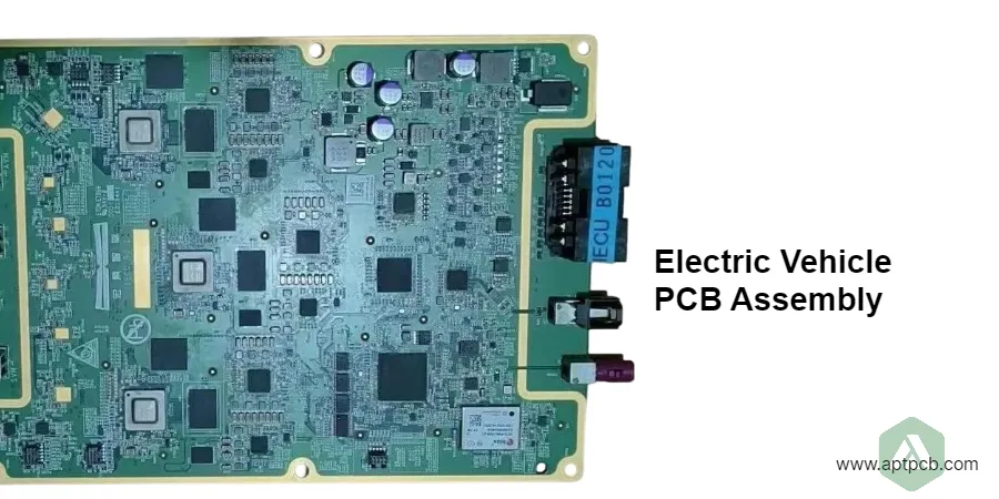
EV PCB assembly requires more than automotive SMT capability. A BMS controller, traction inverter control board, onboard charger, and DC-DC converter each create different manufacturing challenges involving insulation, thermal management, power devices, sensing accuracy, and functional verification.
The correct supplier evaluation starts with a simple question:
Can the assembly process prove that the board will be built, inspected, and tested according to the electrical, thermal, and safety requirements of the EV application?
APTPCB supports EV electronics through turnkey assembly, including PCB fabrication, component sourcing, assembly, inspection, and project-defined testing for BMS, inverter, charging, and power-conversion applications.
Which EV PCB assembly type matches your application requirements?
Different EV electronics assemblies fail in different ways. Classifying the board before supplier selection helps define the correct process controls.
| EV assembly | Main manufacturing challenge | Engineering inputs required | Evidence to request |
|---|---|---|---|
| BMS cell-monitoring board | Measurement leakage, noise, isolation | Cell sensing accuracy, balancing circuits, communication interface | Functional test records, inspection data |
| BMS controller | Mixed HV/LV domains and diagnostics | I/O, firmware, communication, protection functions | Programming verification and functional test |
| Traction inverter PCB | Power switching, thermal stress, parasitics | Power devices, gate drive, thermal interface | Process records, electrical test |
| Onboard charger PCB | HV isolation and power conversion | Input/output ratings, insulation requirements | Isolation test and functional validation |
| DC-DC converter PCB | High current and thermal loading | Current paths, operating range, cooling requirements | Load testing and inspection |
| Charging controller PCB | Communication and protection logic | Protocol interfaces, interlocks, diagnostics | Interface verification |
The PCB assembly supplier should manufacture against released requirements. Vehicle-level safety, EMC, and functional qualification remain separate product-validation activities.
How should high-voltage isolation be specified for EV PCB assembly?
High-voltage EV electronics depend on the complete insulation system, not one spacing number. Creepage and clearance requirements depend on working voltage, transient conditions, insulation class, material properties, pollution environment, and the applicable design standard.
The manufacturing package should identify:
- HV and LV voltage domains;
- insulation type requirements;
- creepage and clearance requirements;
- PCB material characteristics;
- slots, cutouts, coatings, and connector constraints;
- contamination-control requirements;
- dielectric or insulation-resistance testing criteria.
A PCB assembly supplier must preserve the designed isolation path during fabrication and assembly. Component bodies, solder joints, residues, connectors, and coating coverage can change the effective insulation distance.
For production testing, define:
- test voltage;
- test duration;
- leakage limit;
- ramp conditions;
- test locations;
- discharge procedure.
APTPCB can integrate project-defined electrical and inspection requirements with testing and quality controls.
What manufacturing controls are required for SiC traction inverter PCBA?
SiC devices improve switching efficiency and enable higher-performance EV power conversion, but they also increase sensitivity to assembly quality.
A traction inverter PCBA evaluation should focus on three areas.
Power semiconductor attachment
Large power packages create different thermal behavior compared with standard SMT components. Manufacturing planning should consider:
- solder paste volume;
- thermal mass differences;
- reflow profile;
- hidden solder joints;
- voiding requirements;
- inspection method.
Where critical thermal paths depend on concealed joints, visual inspection alone is insufficient.
Gate-drive and switching layout
High-speed switching circuits are sensitive to:
- parasitic inductance;
- component placement;
- isolation devices;
- gate resistor values;
- incorrect substitutions.
Critical gate-drive components should be identified in BOM controls and test documentation.
Thermal interface control
The supplier should understand:
- heatsink interfaces;
- cold plates;
- thermal pads;
- component height limits;
- mechanical mounting requirements.
Manufacturing verification should confirm that the assembled board matches the thermal design intent.
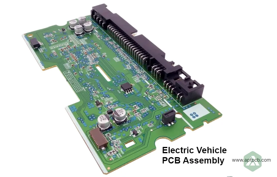
A manufacturing functional test can verify defined board behavior, while inverter efficiency, EMC, thermal performance, and vehicle operation require system-level validation.
Why is BMS PCB assembly different from standard automotive electronics?
BMS assemblies combine precision measurement with high-voltage battery environments. Small leakage currents, contamination, or component variation can affect measurement accuracy.
Important BMS assembly considerations include:
Measurement accuracy
Specify controlled components for:
- voltage sensing networks;
- current measurement circuits;
- temperature inputs;
- isolation interfaces.
The production test should apply known inputs and verify measured outputs against customer-defined limits.
Balancing circuit reliability
Balancing circuits introduce thermal loads. Review:
- resistor power rating;
- copper area;
- temperature rise;
- nearby sensitive components.
Active balancing designs require additional consideration for switching devices, magnetics, and current paths.
BMS production test coverage
Typical verification includes:
- simulated cell-voltage inputs;
- temperature-channel response;
- communication testing;
- balancing activation;
- diagnostic behavior;
- firmware programming verification.
ISO 26262 applies to the lifecycle of safety-related automotive electronic systems. A PCBA manufacturer can provide controlled manufacturing evidence, but assembly alone does not make a board ASIL-qualified.
How do OBC and DC-DC converter PCB assemblies differ?
Onboard chargers and DC-DC converters combine power conversion, control electronics, sensing, magnetics, and thermal requirements.
Manufacturing planning should address:
| Area | Assembly consideration |
|---|---|
| Power components | Package handling, solder profile, inspection |
| Magnetics | Mechanical support, soldering process, thermal impact |
| High-current paths | Copper design and connection reliability |
| Isolation barriers | PCB spacing, connectors, contamination control |
| Mixed technology | SMT plus through-hole or selective solder processes |
| Test access | Safe programming and electrical verification |
Charging protocol compliance and vehicle interoperability remain system-level requirements. The PCBA supplier should verify the functions assigned to manufacturing.
Which EV PCBA failure modes should be reviewed before production?
| Failure mode | Engineering review item | Manufacturing evidence |
|---|---|---|
| Isolation failure | HV/LV spacing and insulation design | Electrical test records |
| Power-device overheating | Thermal path and solder quality | Process data and inspection |
| BMS measurement drift | Component tolerance and cleanliness | BOM verification and functional results |
| Wrong critical component | Approved part control | Traceability records |
| Connector failure | Mechanical and solder requirements | Inspection results |
| Firmware mismatch | Programming control | Revision verification |
A strong EV PCBA process connects each important failure mechanism to a prevention or detection method.
What supplier evidence should EV engineering teams request?
Before production release, define the manufacturing baseline:
- approved PCB revision;
- BOM revision;
- firmware revision;
- approved substitutions;
- inspection requirements;
- functional test limits;
- traceability requirements;
- process controls.
Changes involving power semiconductors, isolation components, PCB materials, solder processes, or thermal interfaces should receive engineering review.
APTPCB's quality system can support manufacturing controls defined for the project, while product qualification remains controlled by customer requirements.
What drives EV PCB assembly cost?
EV PCBA cost is mainly influenced by process complexity.
| Requirement | Cost impact |
|---|---|
| Automotive component sourcing | Traceability and availability control |
| Large power packages | Special assembly and inspection |
| Mixed SMT/THT construction | Additional processes |
| HV testing | Safety equipment and fixtures |
| Functional testing | Custom fixtures and engineering effort |
| Coating or potting | Additional processing |
| Serialization | Manufacturing data management |
Early prototypes should prioritize process learning and test coverage before optimizing unit cost.
EV PCB assembly RFQ checklist
Provide the supplier with:
- Gerber or ODB++ files;
- fabrication drawings;
- BOM with manufacturer part numbers;
- approved alternatives;
- assembly drawings;
- PCB stackup information;
- voltage domains;
- isolation requirements;
- thermal requirements;
- critical component list;
- inspection requirements;
- firmware information;
- functional-test specifications;
- serialization requirements;
- prototype and production quantities.
For HV testing, define voltage, duration, leakage limits, test points, and safety procedures.
For functional testing, define expected inputs, outputs, loads, communication states, and acceptance limits.
Manufacturer responsibility vs. EV product qualification
A reliable sourcing process separates three responsibilities.
PCB/PCBA manufacturing: builds the assembly according to released data, agreed processes, inspections, and tests.
Manufacturing feasibility: confirms that materials, components, assembly processes, and validation methods can achieve the required performance.
Vehicle/product qualification: proves compliance with applicable safety, EMC, environmental, and vehicle requirements.
Keeping these boundaries clear prevents supplier capability claims from being confused with complete product certification.
FAQ
Should prototype EV PCBAs use production-level controls?
Prototype builds should preserve the characteristics needed to evaluate production readiness. Major differences in materials, components, or testing can reduce the value of prototype validation.
When should conformal coating be used on EV PCB assemblies?
Coating should be selected according to environmental and insulation requirements. Material selection, masking, curing, rework, and inspection requirements should be defined before production.
What EV PCBA data should be serialized?
Requirements depend on the program. Common records include board serial number, PCB lot, assembly lot, firmware version, component genealogy, production date, and test status.
Can EV PCB assemblers replace unavailable components?
Only according to approved substitution rules. Power semiconductors, sensing components, isolation devices, and thermal-critical parts require engineering review before replacement.
How should EV PCB revisions be controlled?
Use formal change control to evaluate effects on electrical performance, thermal behavior, safety requirements, manufacturing process, and validation evidence. ```