Farm Management PCB systems are the backbone of modern agricultural automation, controlling everything from automated feeding lines to climate regulation and waste processing. Unlike standard consumer electronics, a Farm Management PCB must survive in harsh environments characterized by high humidity, ammonia concentrations, dust, and fluctuating temperatures. Engineers designing for this sector must prioritize durability and environmental protection to prevent premature field failures.
At APTPCB (APTPCB PCB Factory), we see that the most successful agricultural electronics combine robust layout strategies with specialized protective coatings. This guide covers the specific design rules, manufacturing specifications, and troubleshooting protocols required to build reliable boards for poultry and waste management applications.
Farm Management PCB quick answer (30 seconds)
If you are designing or sourcing a Farm Management PCB, these are the non-negotiable requirements for reliability:
- Environmental Protection is Mandatory: You must apply conformal coating (acrylic, silicone, or urethane) to protect against moisture and ammonia corrosion common in poultry houses.
- Surface Finish Matters: Use ENIG (Electroless Nickel Immersion Gold) rather than HASL. ENIG offers better flatness for fine-pitch components and superior corrosion resistance.
- High Tg Materials: Use FR4 with a High Tg (Glass Transition Temperature) of at least 150°C or 170°C to withstand thermal cycling in outdoor or unconditioned enclosures.
- Wide Trace Widths: Power traces for motors (feeders, fans) should be wider than standard calculations to minimize heat rise; consider 2oz or 3oz copper for high-current paths.
- Isolation: Optically isolate low-voltage logic (sensors/MCU) from high-voltage switching (relays/contactors) to prevent noise and surge damage.
- Validation: Boards must pass salt spray and temperature-humidity bias (THB) testing before mass production.
When Farm Management PCB applies (and when it doesn’t)
Understanding the operational environment is the first step in specifying the correct board.
Use Farm Management PCB standards when:
- High Ammonia Exposure: The device operates inside livestock barns, specifically for Poultry Management PCB applications where ammonia levels are elevated.
- Outdoor Exposure: The equipment controls irrigation or Waste Management PCB systems exposed to rain, condensation, or direct sunlight.
- Vibration & Shock: The PCB is mounted on moving machinery, such as automated tractors, harvesters, or feeding conveyors.
- Unstable Power Grids: The installation site is in a rural area with frequent voltage spikes, requiring robust surge protection and power conditioning on the PCB.
- Long Lifecycle: The equipment is expected to last 5–10 years without maintenance in the field.
Do not use these standards (use standard consumer PCB rules) when:
- Climate Controlled Office: The software management server sits in a clean, air-conditioned farm office.
- Disposable Sensors: Short-term, single-use data loggers that are sealed and discarded after one season (though basic moisture protection still applies).
- Prototyping Bench: Initial code development on a breadboard in a lab (however, move to rugged specs immediately for field trials).
Farm Management PCB rules and specifications (key parameters and limits)
The following table outlines the critical design parameters for agricultural electronics. Adhering to these values reduces the risk of field returns due to environmental stress.
| Rule / Parameter | Recommended Value / Range | Why it matters | How to verify | If ignored |
|---|---|---|---|---|
| Base Material | FR4 High Tg (≥150°C) | Prevents delamination during thermal cycling in unconditioned barns. | Check datasheet (e.g., Isola 370HR). | Board warpage or barrel cracks. |
| Copper Weight | 2oz (70µm) or higher | Handles current for motors/actuators; mechanical strength. | Microsection analysis. | Overheating traces; open circuits. |
| Surface Finish | ENIG (Immersion Gold) | Resists oxidation/corrosion better than HASL in humid air. | Visual inspection; X-ray. | Pad corrosion; solder joint failure. |
| Conformal Coating | Silicone or Urethane (Type SR/UR) | Blocks moisture, dust, and ammonia from reaching metal. | UV light inspection (if tracer added). | Short circuits from dendrite growth. |
| Trace Spacing | ≥ 8 mil (0.2mm) | Reduces risk of arcing due to dust/moisture accumulation. | DRC (Design Rule Check) in CAD. | Arcing; leakage currents. |
| Via Protection | Tented or Plugged | Prevents chemicals/moisture from trapping in via barrels. | Visual inspection. | Corrosion inside vias; long-term failure. |
| Solder Mask | Green (High Dam) | Standard green often has best chemical resistance properties. | Chemical resistance test. | Mask peeling; copper exposure. |
| Component Rating | Industrial (-40°C to +85°C) | Ensures operation during winter freezes and summer heat. | BOM review. | System freezes or resets in extreme weather. |
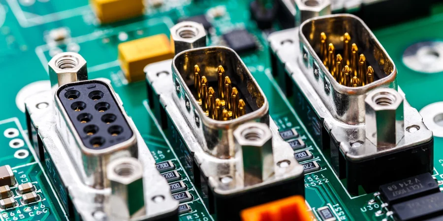
| Connector Plating | Gold Flash or Hard Gold | Prevents fretting corrosion under vibration. | Datasheet verification. | Intermittent signal loss. |
| Test Points | Corrosion-resistant pads | Allows field diagnostics without scraping coating. | ICT fixture check. | Cannot troubleshoot in field. |
| Power Isolation | Optocouplers / Galvanic | Protects MCU from inductive kickback of pumps/fans. | Schematic review. | MCU burnout; random resets. |
| IP Rating (Enclosure) | IP65 or IP67 | The PCB relies on the enclosure for primary defense. | Water ingress test. | Catastrophic water damage. |
Farm Management PCB implementation steps (process checkpoints)

Designing a reliable Poultry Management PCB or general agricultural controller requires a disciplined workflow. Follow these steps to ensure the final product meets industrial standards.
Environmental Profiling
- Action: Measure the target environment's temperature range, humidity, and chemical presence (e.g., ammonia, pesticides).
- Key Parameter: Maximum operating temperature and chemical concentration.
- Check: Does the BOM support -40°C to +85°C?
Schematic Design with Protection
- Action: Add TVS diodes, fuses, and filtering capacitors on all I/O and power lines.
- Key Parameter: Surge rating (e.g., 2kV for power lines).
- Check: Are all sensor inputs protected against static discharge and over-voltage?
Stackup and Material Selection
- Action: Select a High Tg laminate and define copper weight based on current requirements.
- Key Parameter: Heavy Copper PCB capability (2oz+).
- Check: Confirm impedance control if using long-range wireless modules (LoRa/Zigbee).
Layout for High Voltage/Current
- Action: Separate low-voltage logic from high-voltage AC relays by at least 3mm (creepage).
- Key Parameter: Creepage and clearance distances.
- Check: Run a High Voltage DRC.
Design for Manufacturing (DFM) Review
- Action: Submit Gerbers to the manufacturer to check for acid traps and solder mask slivers.
- Key Parameter: Minimum annular ring (ensure it is robust, e.g., 6 mil).
- Check: Manufacturer approval report.
Prototype Fabrication & Assembly
- Action: Produce a small batch (5-10 units) with the specified surface finish (ENIG).
- Key Parameter: Solder joint quality (IPC-A-610 Class 2 or 3).
- Check: Visual inspection and functional test.
Conformal Coating Application
- Action: Apply coating to the PCBA, masking off connectors and sensors.
- Key Parameter: Coating thickness (typically 25-75µm).
- Check: UV inspection to ensure full coverage.
Accelerated Life Testing
- Action: Subject the prototype to thermal cycling and salt mist.
- Key Parameter: Functionality after 48-96 hours of stress.
- Check: No corrosion or signal degradation.
Field Trial (Beta)
- Action: Install units in a real farm setting for 30 days.
- Key Parameter: Uptime and error logs.
- Check: Verify no false triggers from electrical noise.
Farm Management PCB troubleshooting (failure modes and fixes)
Even with robust design, failures can occur. Use this guide to diagnose issues in Waste Management PCB systems and other farm electronics.
Symptom: Intermittent Sensor Readings
- Cause: Vibration from machinery causing connector fretting or cold solder joints.
- Check: Inspect connector pins for black oxidation; check solder joints for cracks.
- Fix: Re-solder joints; replace connectors with gold-plated versions; apply locking glue.
- Prevention: Use locking connectors (e.g., Molex) and add strain relief to cables.
Symptom: Green/Black Corrosion on Pads
- Cause: Ammonia or moisture ingress reacting with copper/solder.
- Check: Inspect edges of the board and areas where coating might be thin.
- Fix: Clean with isopropyl alcohol (if minor); usually requires board replacement.
- Prevention: Improve PCB Conformal Coating process; switch to potting for extreme cases.
Symptom: MCU Resetting Randomly
- Cause: EMI/RFI from large motors or pumps sharing the power line.
- Check: Monitor power rails with an oscilloscope during motor startup.
- Fix: Add external ferrite beads; improve decoupling capacitors.
- Prevention: Optically isolate all I/O; use a separate power supply for logic.
Symptom: Board Overheating
- Cause: Dust accumulation acting as insulation, or undersized traces for current.
- Check: Measure temperature with a thermal camera; check for dust layers.
- Fix: Clean the board; improve enclosure ventilation (with filters).
- Prevention: Increase copper weight; design vertical mounting to reduce dust settling.
Symptom: Wireless Link Failure
- Cause: Metal structures (barns/silos) blocking RF signals.
- Check: RSSI (Received Signal Strength Indicator) levels.
- Fix: Relocate antenna outside the enclosure using a pigtail cable.
- Prevention: Simulate RF propagation; use lower frequency bands (e.g., 900MHz) for better penetration.
Symptom: LCD/Display Fogging
- Cause: Humidity entering the enclosure and condensing on the screen.
- Check: Inspect enclosure seals and gaskets.
- Fix: Add desiccant packs inside the enclosure.
- Prevention: Use optical bonding for displays; ensure IP67 sealing.
How to choose Farm Management PCB (design decisions and trade-offs)
When finalizing your design, you will face several trade-offs. Here is how to navigate them for agricultural applications.
Rigid vs. Flex PCB For most farm applications, Rigid PCBs are the standard choice due to cost-effectiveness and mechanical strength. Flex PCBs are generally avoided unless necessary for a dynamic sensor arm, as they are more susceptible to mechanical damage during installation and maintenance in rough environments. If flexibility is needed for installation only, consider Rigid-Flex PCB designs where the flexible part is protected inside the housing.
Surface Finish: ENIG vs. HASL While HASL (Hot Air Solder Leveling) is cheaper, it is not recommended for farm environments. The uneven surface can lead to poor solder joints on fine-pitch parts, and the exposed alloy is less resistant to corrosion than gold. ENIG is the superior choice for long-term reliability in humid, ammonia-rich air.
Connectors: Through-Hole vs. SMT Prefer Through-Hole connectors for any interface that will be plugged/unplugged by a technician. Surface Mount (SMT) connectors can rip off the pads under mechanical stress. If SMT is required, add mechanical hold-downs or reinforcement vias.
Protection: Coating vs. Potting Conformal Coating is sufficient for most humidity and dust issues and allows for repair. Potting (encapsulating the entire board in resin) offers maximum protection against vibration and submersion but makes repair impossible. Choose potting for submersible pumps or sensors located inside waste pits.
Farm Management PCB FAQ (cost, lead time, common defects, acceptance criteria, Design for Manufacturing (DFM) files)
1. How does the cost of a Farm Management PCB compare to a standard PCB? A Farm Management PCB typically costs 15-30% more than a standard consumer board. The increase is due to higher-grade materials (High Tg FR4), thicker copper (2oz+), ENIG finish, and the application of conformal coating.
2. What is the typical lead time for manufacturing these boards? Standard lead time is 2-3 weeks. This includes extra time for the conformal coating process, which requires curing, and additional quality control steps like ionic contamination testing.
3. Can I use standard FR4 for Poultry Management PCB applications? It is risky. Standard FR4 (Tg 130-140°C) may delaminate or soften if the poultry house gets very hot or if the board generates significant self-heat. High Tg (170°C) material is safer for reliability.
4. What are the acceptance criteria for conformal coating? According to IPC-A-610, the coating must be uniform, transparent, and free of bubbles or voids that bridge conductors. It must cover all conductive surfaces except for masked areas (connectors, test points).
5. How do I test for ammonia resistance? There is no standard "ammonia test" in basic PCB fabrication, but you can request a "Mixed Flowing Gas" (MFG) test during qualification. For the PCB itself, ensuring a high-quality solder mask and ENIG finish is the primary defense.
6. What files are needed for DFM review of a Farm Management PCB? You need to send Gerber files (RS-274X), a Drill file, a BOM (Bill of Materials), and a fabrication drawing that specifies the conformal coating type and masking areas.
7. Why do my boards fail in Waste Management PCB applications? Waste environments often produce hydrogen sulfide and methane. If the board is not potted or heavily coated, these gases attack the silver and copper, causing "black pad" or open circuits.
8. Is X-ray inspection necessary? Yes, if you are using BGA components or QFNs. Since these boards are often coated, reworking them is difficult, so ensuring zero defects during assembly via X-ray is critical.
9. Can APTPCB handle the conformal coating process? Yes, APTPCB offers in-house conformal coating services, including masking and UV inspection, ensuring the board is field-ready upon delivery.
10. What is the best way to prevent lightning damage in farm electronics? PCBs should include Gas Discharge Tubes (GDTs) and MOVs (Metal Oxide Varistors) at the power entry point. A solid ground plane and proper chassis grounding are also essential.
11. How thick should the PCB be? Standard 1.6mm is common, but for larger boards subject to vibration (e.g., on a tractor), 2.0mm or 2.4mm thickness provides better mechanical rigidity and reduces vibration-induced fatigue.
12. Do I need impedance control for farm sensors? Only if you are using high-speed communication interfaces or RF modules (like LoRa or Wi-Fi) directly on the board. For standard analog sensors (4-20mA), impedance control is usually not required.
Resources for Farm Management PCB (related pages and tools)
- Industrial Control PCB: Explore manufacturing capabilities for rugged industrial controllers similar to farm systems.
- PCB Conformal Coating: Detailed information on coating types and processes essential for agricultural protection.
- Heavy Copper PCB: Learn about high-current capabilities for driving motors and actuators in farm machinery.
- High Tg PCB: Specifications for heat-resistant materials suitable for unconditioned farm environments.
Farm Management PCB glossary (key terms)
| Term | Definition | Relevance to Farm PCB |
|---|---|---|
| Conformal Coating | A protective chemical film applied to the PCBA. | Essential barrier against moisture, dust, and ammonia. |
| IP67 | Ingress Protection rating (Dust tight, immersion up to 1m). | The target rating for enclosures used in wash-down areas. |
| High Tg | High Glass Transition Temperature (thermal limit of resin). | Prevents board expansion/failure in hot barns or outdoor boxes. |
| ENIG | Electroless Nickel Immersion Gold surface finish. | Provides superior corrosion resistance compared to HASL. |
| LoRaWAN | Long Range Wide Area Network protocol. | Common wireless standard for farm sensors due to long range. |
| Ammonia Corrosion | Chemical attack on copper caused by animal waste. | The primary failure mode in poultry and swine electronics. |
| Potting | Encapsulating the entire PCBA in resin. | Used for submersible or extremely harsh waste management sensors. |
| Creepage | Shortest distance between two conductors along the surface. | Must be maximized to prevent arcing in dusty/humid conditions. |
| BOM | Bill of Materials. | Must specify "Industrial Grade" (-40 to +85°C) parts. |
| Gerber Files | Standard file format for PCB fabrication. | Must include layers for solder mask and paste. |
| DFM | Design for Manufacturing. | Checks if the rugged design is actually manufacturable. |
| Salt Spray Test | Accelerated corrosion test. | Validates the effectiveness of the coating and enclosure. |
Request a quote for Farm Management PCB (Design for Manufacturing (DFM) review + pricing)
Ready to manufacture your agricultural electronics? At APTPCB, we specialize in high-reliability boards for harsh environments. Send us your design files, and our engineers will perform a comprehensive DFM review to ensure your board can withstand the rigors of the farm.
What to include in your request:
- Gerber Files: RS-274X format.
- Fabrication Drawing: Specify "Conformal Coating Required" and type (e.g., Silicone).
- Volume: Prototype quantity vs. Mass production estimate.
- Special Requirements: Copper thickness, specific laminate (e.g., Isola), or testing needs (e.g., functional test).
Conclusion (next steps)
Designing a successful Farm Management PCB requires more than just connecting components; it demands a defensive strategy against the environment. By selecting the right materials, enforcing strict layout rules for power and isolation, and applying rigorous protection like conformal coating, you can build systems that last for years in the field. Whether you are building a Poultry Management PCB or a Waste Management PCB controller, prioritizing these specifications will reduce maintenance costs and ensure reliable operation.