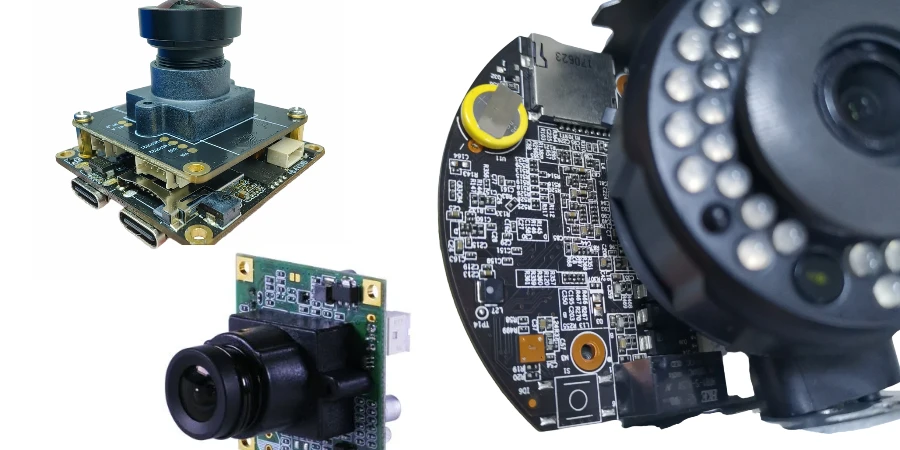
Perimeter security systems rely heavily on the reliability of the Fence Detection PCB. These circuit boards process signals from vibration sensors, accelerometers, or triboelectric cables to distinguish between a genuine intrusion attempt and environmental noise. Because these units operate outdoors 24/7, the manufacturing requirements differ significantly from standard indoor electronics. APTPCB (APTPCB PCB Factory) specializes in fabricating these ruggedized boards with strict adherence to environmental and signal integrity standards.
Fence Detection PCB quick answer (30 seconds)
- Environmental Hardening is Mandatory: Boards must withstand -40°C to +85°C and high humidity. Conformal coating (acrylic or silicone) is not optional; it is a requirement to prevent dendritic growth.
- Signal-to-Noise Ratio (SNR): The PCB layout must isolate sensitive analog sensor lines from digital processing noise to prevent false alarms caused by internal interference.
- Vibration Resilience: Since these boards are mounted directly on fences, components must be secured against constant mechanical vibration. Heavy components require bonding or underfill.
- Tamper Protection: Designs often require integrated tamper switches or conductive loops to trigger an alarm if the enclosure is opened or the board is drilled.
- Power Efficiency: Many fence nodes are solar or battery-powered. Low-leakage PCB materials and efficient power management layouts are critical for longevity.
- Frequency Requirements: For microwave or Radar Detection PCB variants, controlled impedance and high-frequency laminates (like Rogers or Teflon) are necessary to maintain detection range.
When Fence Detection PCB applies (and when it doesn’t)
Use Fence Detection PCB logic when:
- Perimeter Security: You are designing systems for prisons, airports, or critical infrastructure requiring PIDS (Perimeter Intrusion Detection Systems).
- Vibration Analysis: The system uses MEMS accelerometers or piezo sensors to detect cutting, climbing, or lifting of the fence fabric.
- Outdoor Deployment: The electronics will be exposed to rain, snow, UV radiation, and extreme temperature cycles.
- Long-Distance Cabling: The PCB acts as a signal processor or repeater for long runs of sensor cable (triboelectric or fiber optic).
- Anti-Tamper Requirements: The application demands immediate notification if the hardware is physically attacked.
Do not use standard PCB logic when:
- Indoor Motion Detection: Standard PIR sensor PCBs are cheaper and do not require the ruggedization of fence-mounted units.
- Short-Range Consumer Tech: If the device is a simple residential doorbell, the industrial-grade specs of a Fence Detection PCB are overkill.
- Non-Critical Monitoring: If a false negative (missed intrusion) is acceptable, lower-cost FR4 materials without conformal coating might suffice (though not recommended).
- High-Bandwidth Data: Unless it is a video-integrated unit, fence sensors typically transmit low-bandwidth status data, not high-speed video streams.
Fence Detection PCB rules and specifications (key parameters and limits)
The following table outlines the critical design and manufacturing parameters for a robust Fence Detection PCB. Ignoring these often leads to high Nuisance Alarm Rates (NAR).
| Rule | Recommended Value/Range | Why it matters | How to verify | If ignored |
|---|---|---|---|---|
| Base Material (Standard) | High-Tg FR4 (Tg > 170°C) | Prevents delamination during thermal cycling outdoors. | TMA / DSC analysis | Board failure in summer/winter cycles. |
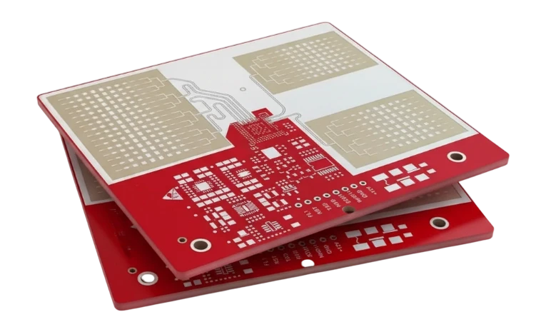
| Base Material (Radar) | Rogers 4000 series or Taconic | Low dielectric loss is required for Radar Detection PCB frequencies (24GHz+). | Dk/Df measurement | Reduced detection range; signal attenuation. |
| Copper Weight | 1 oz to 2 oz | Ensures durability and current handling for POE (Power over Ethernet) runs. | Microsection analysis | Voltage drop over long fence lines. |
| Conformal Coating | Acrylic (AR) or Silicone (SR) | Blocks moisture, salt mist, and fungus. | UV light inspection | Corrosion; short circuits; false alarms. |
| Solder Mask | Matte Green or Black | Matte finish reduces solder balling; specific colors aid thermal management. | Visual inspection | Minor impact, but gloss can reflect UV. |
| Component Anchoring | Bonding/Underfill for >5g parts | Fence vibration can fatigue solder joints on heavy capacitors/inductors. | Vibration testing | Components fall off; intermittent failures. |
| Trace Width (Analog) | > 8 mil (where possible) | Reduces resistance and susceptibility to minor manufacturing variations. | AOI (Automated Optical Inspection) | Noisy sensor readings. |
| Impedance Control | ±10% or ±5% | Critical for RS-485 comms or RF radar signals. | TDR (Time Domain Reflectometry) | Communication errors; data packet loss. |
| Surface Finish | ENIG (Electroless Nickel Immersion Gold) | Excellent flatness for SMT; corrosion resistant. | X-Ray Fluorescence | HASL may oxidize in harsh outdoor air. |
| Via Tenting | 100% Plugged or Tented | Prevents moisture ingress through vias. | Visual / Cross-section | Water accumulation inside vias; corrosion. |
| Tamper Loop | Continuous trace on perimeter | Detects if the board edges are cut or broken. | Continuity test | Security vulnerability; bypass capability. |
| Test Points | Accessible without disassembly | Allows field technicians to calibrate sensitivity. | ICT fixture check | High maintenance costs; difficult calibration. |
Fence Detection PCB implementation steps (process checkpoints)

Follow these steps to move from concept to a field-ready Fence Detection PCB.
- Define Sensor Type & Frequency: Determine if the system relies on low-frequency vibration (MEMS), audio frequencies (microphonic cable), or high-frequency RF (Radar Detection PCB). This dictates the stack-up.
- Select Laminate Material: Choose High-Tg FR4 for standard vibration sensors. For radar or microwave barriers, select low-loss PTFE-based materials.
- Schematic Capture with Protection: Include TVS diodes and gas discharge tubes on all I/O lines. Lightning surges are common on long fence lines.
- Layout for Noise Immunity: Separate analog sensor grounds from digital logic grounds. Use a star ground topology to prevent ground loops.
- DFM Review: Send Gerber files to APTPCB for a Design for Manufacturing check. Verify that annular rings are sufficient for the specified copper weight.
- Prototype Fabrication: Produce a small batch (5-10 units). Ensure the PCB conformal coating process is validated during this stage.
- Environmental Stress Screening (ESS): Subject the prototypes to thermal cycling (-40°C to +85°C) and vibration testing that mimics fence movement.
- Field Calibration: Install units on a test fence. Adjust gain and filter settings to maximize Probability of Detection (POD) while minimizing False Alarm Rate (FAR).
- Tamper Validation: Verify that opening the enclosure or cutting the Tamper Detection PCB traces triggers an immediate alarm.
- Mass Production: Lock the BOM and assembly instructions. Ensure every production batch undergoes Automated Optical Inspection (AOI) and In-Circuit Testing (ICT).
Fence Detection PCB troubleshooting (failure modes and fixes)
When a Fence Detection PCB fails in the field, it usually manifests as false alarms or dead zones.
Symptom: High False Alarm Rate (Wind/Rain)
- Cause: Gain is too high, or PCB noise floor is too high.
- Check: Measure power supply ripple. Check for moisture bridging traces.
- Fix: Improve power filtering capacitors. Re-apply conformal coating if gaps are found.
- Prevention: Use differential signaling for sensors to cancel out common-mode noise.
Symptom: Intermittent Signal Loss
- Cause: Solder joint fatigue due to fence vibration.
- Check: Inspect heavy components (transformers, large caps) for cracked joints.
- Fix: Reflow and apply adhesive bonding (staking) to heavy parts.
- Prevention: Specify component staking in the assembly drawing.
Symptom: Dead Unit after Storm
- Cause: Lightning surge or electrostatic discharge (ESD).
- Check: Inspect TVS diodes and fuses near the connector. Look for burnt traces.
- Fix: Replace protection components. Repair burnt traces if inner layers are intact.
- Prevention: Upgrade surge protection rating; ensure proper earth grounding of the fence and PCB.
Symptom: Corrosion on Pads
- Cause: Enclosure seal failure or insufficient surface finish.
- Check: Look for green/white residue on pads.
- Fix: Clean with IPA, repair solder, and apply heavy silicone coating.
- Prevention: Switch to ENIG surface finish and IP67 or IP68 enclosures.
Symptom: Radar Blind Spots
- Cause: Impedance mismatch or wrong laminate dielectric constant.
- Check: Verify stack-up and trace width. Check if the radome (cover) material is blocking RF.
- Fix: Respin PCB with correct controlled impedance.
- Prevention: Use TDR testing during manufacturing to validate impedance.
Symptom: Tamper Alarm Stuck On
- Cause: Broken trace in the tamper loop or faulty switch.
- Check: Continuity test on the tamper circuit.
- Fix: Jumper the broken trace (temporary) or replace the switch.
- Prevention: Widen tamper traces to prevent hairline fractures during handling.
How to choose Fence Detection PCB (design decisions and trade-offs)
Selecting the right architecture depends on the specific threat model and budget.
Vibration/MEMS vs. Radar Detection PCB
- Vibration (MEMS): Best for detecting cutting or climbing on chain-link fences. Lower cost. Requires a PCB at regular intervals (nodes).
- Radar: Best for open areas or "virtual fences." The Radar Detection PCB is more expensive due to high-frequency materials but covers a volume, not just the fence fabric.
Distributed vs. Centralized Processing
- Distributed (Smart Nodes): Each Fence Detection PCB has a microcontroller (MCU) to process signals locally.
- Pros: Scalable, single point of failure doesn't kill the whole system.
- Cons: Higher cost per node; more firmware to manage.
- Centralized (Analyzer): Simple sensor PCBs send raw analog signals to a central analyzer.
- Pros: Cheaper sensor nodes; centralized intelligence.
- Cons: Analog signals degrade over long cables; central failure disables a whole zone.
Rigid vs. Flex-Rigid
- Rigid PCB: Standard for most fence sensors mounted in boxes.
- Rigid-Flex: Useful if the sensor needs to conform to a curved fence post or fit into a compact, cylindrical housing. See Rigid-Flex PCB capabilities for complex geometries.
Fence Detection PCB FAQ (cost, lead time, common defects, acceptance criteria, Design for Manufacturability (DFM) files)
Q: What is the typical lead time for a Fence Detection PCB prototype? A: Standard lead time is 5-7 days for FR4 boards. For Radar Detection PCB designs using Rogers materials, allow 10-15 days for material procurement.
Q: How much does a Fence Detection PCB cost? A: A simple vibration sensor node (2-layer, FR4) costs $2-$5 in volume. A complex radar board (4-layer, Rogers/Hybrid) can cost $20-$50 per unit depending on size and gold plating requirements.
Q: What testing is required for these boards? A: Beyond standard E-test (Open/Short), we recommend TDR for impedance, ionic contamination testing (to prevent corrosion), and functional testing with simulated sensor inputs.
Q: Can you manufacture PCBs for Thermal Detection systems? A: Yes. Thermal Detection PCB designs often require metal core (MCPCB) or heavy copper to dissipate heat from the sensor or processing unit.
Q: What files are needed for a DFM review? A: Gerber files (RS-274X), Drill files, IPC netlist, Stack-up diagram, and Assembly drawings (pick-and-place). Specify conformal coating areas clearly.
Q: How do I specify the tamper detection loop? A: Include a specific layer or trace in your Gerber files labeled "Tamper Loop." Ensure it runs along the board perimeter and connects to the detection circuit.
Q: What is the best surface finish for outdoor PCBs? A: ENIG is preferred over HASL. It is flatter for fine-pitch components and more resistant to oxidation before the conformal coating is applied.
Q: How do you handle "nuisance alarms" from a PCB manufacturing perspective? A: We focus on signal integrity. By ensuring consistent impedance and low-noise power planes, we eliminate hardware-induced noise, leaving only software tuning to handle environmental factors.
Q: Do you support high-frequency laminates for microwave barriers? A: Yes, APTPCB stocks materials from Rogers, Taconic, and Isola suitable for 24GHz and 77GHz radar applications.
Q: What is the acceptance criteria for conformal coating? A: We follow IPC-A-610 Class 3 standards for coating thickness and coverage. No bubbles, voids, or de-wetting on critical component leads.
Fence Detection PCB glossary (key terms)
| Term | Definition | Context |
|---|---|---|
| PIDS | Perimeter Intrusion Detection System | The overarching system where the PCB is used. |
| MEMS | Micro-Electro-Mechanical Systems | Tiny sensors on the PCB that detect acceleration/vibration. |
| Triboelectric | Charge generation via friction | A type of sensor cable processed by the PCB. |
| Conformal Coating | Protective chemical layer | Essential for waterproofing outdoor PCBs. |
| FAR | False Alarm Rate | The frequency of alarms caused by wind, animals, or noise. |
| NAR | Nuisance Alarm Rate | Alarms caused by non-intrusion events (similar to FAR). |
| POD | Probability of Detection | The likelihood the PCB correctly identifies an intruder. |
| Zone | A specific section of the fence | One PCB usually monitors 1 or 2 zones. |
| Tamper Switch | Electromechanical device | Triggers alarm if the PCB enclosure is opened. |
| Masking | Ignoring specific signal patterns | Software/Hardware filtering to ignore rain noise. |
| Hybrid Stack-up | Mixed material layers | Combining FR4 and Rogers in one Radar Detection PCB to save cost. |
| POE | Power over Ethernet | Common method to power fence sensors via the data cable. |
Request a quote for Fence Detection PCB (Design for Manufacturability (DFM) review + pricing)
APTPCB provides specialized manufacturing services for security and defense electronics. Send us your design files for a comprehensive DFM review that checks for outdoor durability, impedance control, and manufacturability.
What to include in your request:
- Gerber Files: RS-274X format.
- Fabrication Drawing: Specify material (e.g., FR4, Rogers), copper weight, and surface finish.
- Assembly BOM: If PCBA is required.
- Special Requirements: Conformal coating type, impedance constraints, or security equipment PCB standards.
Conclusion (next steps)
Designing a Fence Detection PCB requires balancing extreme sensitivity with rugged environmental protection. Whether you are building a vibration-based system, a Radar Detection PCB, or a Thermal Detection PCB, the manufacturing quality directly impacts the security of the facility. By selecting the right materials, enforcing strict layout rules, and applying robust testing protocols, you ensure your system detects threats accurately while minimizing false alarms. APTPCB is ready to support your project from prototype to mass production with industrial-grade reliability.