Contents
- The Context: What Makes Filtration Control PCB Challenging
- The Core Technologies (What Actually Makes It Work)
- Ecosystem View: Related Boards / Interfaces / Manufacturing Steps
- Comparison: Common Options and What You Gain / Lose
- Reliability & Performance Pillars (Signal / Power / Thermal / Process Control)
- The Future: Where This Is Going (Materials, Integration, Ai/automation)
- Request a Quote / DFM Review for Filtration Control PCB (What to Send)
- Conclusion
For engineers and procurement teams at APTPCB (APTPCB PCB Factory), a "good" Filtration Control PCB is defined not just by its ability to switch a relay, but by its resilience. It must operate flawlessly in environments that are inherently hostile to electronics—high humidity, chemical vapors, constant vibration, and electromagnetic interference from heavy inductive loads. This article explores the narrative of designing and manufacturing these critical boards, moving beyond basic specifications to understand the engineering trade-offs that ensure longevity and performance.
Highlights
- Quick rules and recommended ranges.
- How to verify and what to log as evidence.
- Common failure modes and fastest checks.
- Decision rules for trade-offs and constraints.
The Context: What Makes Filtration Control PCB Challenging
Designing electronics for filtration is fundamentally different from designing for consumer gadgets or even standard server rooms. The primary challenge is the environment. Filtration implies the presence of contaminants—particulates, fluids, and often corrosive chemicals. A standard FR4 board left unprotected in a chlorine-rich water treatment room will suffer from copper corrosion and dendritic growth within months, leading to short circuits.
Furthermore, the electrical environment is noisy. Filtration systems rely on pumps, compressors, and solenoid valves. When a large pump motor kicks on, it generates significant inrush current and electromagnetic interference (EMI). When a solenoid valve snaps shut, it creates a voltage spike (back EMF) that can fry sensitive microcontrollers if not properly snubbed. The PCB must act as a bridge between the delicate 3.3V logic of the microcontroller and the harsh 24V, 110V, or 220V reality of the actuators.
Lead time and lifecycle management also play a crucial role. Industrial filtration systems are capital-intensive assets expected to last 10 to 20 years. The PCB design must rely on components that will remain available for decades, or be designed with enough flexibility to accept alternatives without a complete redesign. This pressure forces designers to prioritize robust, proven technologies over the absolute latest, potentially volatile components.
Finally, there is the issue of density versus isolation. As systems become smarter, integrating IoT connectivity and advanced sensor arrays, the PCB layout becomes crowded. Yet, safety standards require strict creepage and clearance distances between high-voltage power sections and low-voltage logic sections. Balancing these opposing forces—miniaturization for compact enclosures versus physical separation for safety—is the central tension in modern Industrial Control PCB design.
The Core Technologies (What Actually Makes It Work)
To understand how a Filtration Control PCB functions, we must look at the specific technologies that enable it to sense, decide, and act. These are not just isolated components but integrated subsystems that define the board's architecture.
Mixed-Signal Sensor Interfaces
The eyes and ears of a filtration system are its sensors: differential pressure transducers (to measure filter clogging), flow meters, pH sensors, and turbidity sensors. These devices often output analog signals, such as the industrial standard 4-20mA current loop or 0-10V voltage signals. The PCB must include precision Analog-to-Digital Converters (ADCs) and operational amplifiers to condition these signals. Crucially, because the sensors are often located meters away from the PCB on long cables, the inputs must be protected against electrostatic discharge (ESD) and induced noise. A robust design often employs optocouplers to electrically isolate the sensitive processor from the field wiring, preventing a surge in a sensor cable from destroying the main CPU.
Power Electronics and Actuation
Once the logic decides a filter backwash is needed, the PCB must drive the physical world. This involves switching high-power loads.
- Relays vs. Solid State: Mechanical relays are robust and provide galvanic isolation but wear out over time. Solid State Relays (SSRs) or MOSFETs offer infinite switching cycles but generate heat and require careful thermal management.
- Inductive Load Handling: Driving a solenoid valve is easy; turning it off is hard. The collapsing magnetic field generates a high-voltage spike. Flyback diodes or snubber circuits are mandatory on the PCB to clamp this voltage and protect the driver transistors.
- Heavy Copper Traces: For boards driving large pumps directly, standard 1oz copper may be insufficient. Heavy Copper PCB technology (2oz, 3oz, or more) is frequently used to carry high current without excessive resistive heating, ensuring the board remains cool even under load.
Environmental Protection Strategies
Since the PCB lives near fluids, moisture ingress is the enemy.
- Conformal Coating: This is the first line of defense. A thin layer of acrylic, silicone, or urethane is applied over the assembled board (PCBA) to seal out moisture and dust. For extreme environments, potting (encapsulating the entire board in epoxy) might be necessary.
- Design for Coating: The layout must accommodate coating. Connectors and test points often need to be masked off during the coating process. Designers must leave adequate spacing around components to ensure the coating flows evenly and doesn't bridge pins or leave voids where moisture can accumulate.
- Corrosion-Resistant Finishes: The choice of surface finish on the bare PCB matters. While OSP (Organic Solderability Preservative) is cheap, it degrades quickly in harsh air. ENIG (Electroless Nickel Immersion Gold) is the standard for high-reliability filtration boards because gold is inert and does not corrode, ensuring reliable solder joints and contact points over years of service.
Ecosystem View: Related Boards / Interfaces / Manufacturing Steps
The Filtration Control PCB rarely operates in isolation. It is usually part of a larger ecosystem of electronics and electromechanical hardware. Understanding this context is vital for successful manufacturing and integration.
The Hmi Connection
The main control board often connects to a Human Machine Interface (HMI)—a display panel or touchscreen where operators view system status. This connection is typically digital (RS-485, Modbus, CAN bus, or Ethernet). The PCB design must include robust transceiver chips for these protocols. In many modern systems, the HMI is a separate board mounted to the enclosure door, connected via a ribbon cable or harness. Ensuring signal integrity over this cable, especially in a cabinet full of noisy motor starters, requires careful impedance matching and often the use of differential signaling.
Sensor and Actuator Breakouts
In complex filtration skids, wiring everything directly to the main PCB can create a "rat's nest" of cables that is difficult to service. Often, the ecosystem includes smaller breakout boards or passive distribution PCBs located closer to the valves and sensors. These satellite boards aggregate signals and send them back to the main controller via a single multi-conductor cable. This modular approach simplifies maintenance—if a sensor port is damaged, only the cheap breakout board needs replacing, not the expensive main controller.
Assembly and Box Build
Manufacturing a Filtration Control PCB extends beyond Surface Mount Technology (SMT). It often involves significant Through-Hole Technology (THT) for bulky connectors, large capacitors, and relays. Furthermore, the final product is frequently delivered as a "Box Build"—the PCB is installed into an enclosure, cable harnesses are connected, and the unit is potted or coated.
- Testing: Functional Circuit Testing (FCT) is critical. The test fixture must simulate the sensors (injecting 4-20mA signals) and provide dummy loads for the outputs to verify the board can drive the required current.
- Burn-In: High-reliability boards often undergo burn-in testing, where they are powered up and operated at elevated temperatures for hours or days to weed out infant mortality failures before they reach the field.
- See Box Build Assembly for more on how these complete units are integrated.
Comparison: Common Options and What You Gain / Lose
When specifying a Filtration Control PCB, engineers face several branching paths. Should you use a standard rigid board or a rigid-flex for tight spaces? Is a simple 2-layer board sufficient, or does the noise environment demand a 4-layer stackup with dedicated ground planes? The choices made here ripple through to cost, reliability, and lead time.
Below is a decision matrix that highlights how technical choices translate into practical outcomes in the field.
Decision Matrix: Technical Choice → Practical Outcome
| Technical choice | Direct impact |
|---|---|
| Surface Finish: HASL vs. ENIG | HASL is cheaper but uneven; ENIG provides a flat surface for fine-pitch components and superior corrosion resistance in humid pump rooms. |
| Layer Count: 2-Layer vs. 4-Layer | 4-Layer allows for internal ground/power planes, significantly reducing EMI susceptibility from pumps and improving signal integrity for sensors. |
| Protection: Conformal Coating vs. Potting | Coating protects against humidity and dust (repairable); Potting offers total waterproof/vibration proofing but makes the board unrepairable and heavier. |
| Copper Weight: 1oz vs. 2oz+ | Standard 1oz is fine for logic; 2oz+ is required if the PCB traces directly drive high-current solenoids or motors to prevent overheating. |
For a deeper dive into surface finishes, specifically why ENIG is often preferred for industrial controls, refer to our guide on PCB Surface Finishes.
Reliability & Performance Pillars (Signal / Power / Thermal / Process Control)
Reliability in filtration control is not an accident; it is a result of deliberate design choices across four key pillars.
1. Signal Integrity in a Noisy World
The most common failure mode in filtration controls is not the board dying, but the board acting "glitchy." A pressure sensor reading fluctuates wildly when a pump starts, causing the system to trigger a false backwash cycle. This is a signal integrity issue.
- Grounding: A solid ground plane is essential. Star grounding techniques prevent high currents from motor drivers from flowing through the sensitive analog ground paths of the sensor inputs.
- Filtering: Inputs must have hardware low-pass filters (RC networks) to strip out high-frequency noise before the signal reaches the ADC. Software filtering alone is often insufficient against strong industrial noise.
2. Thermal Management
Heat kills electronics. In a sealed NEMA-rated enclosure, there is no airflow. The PCB must dissipate heat generated by voltage regulators and MOSFETs into the chassis or through the board itself.
- Thermal Vias: Placing arrays of small holes (vias) under hot components helps transfer heat to the ground plane on the opposite side of the board, which acts as a heat spreader.
- Component Spacing: Power components should be spaced apart to avoid hotspots. Placing a hot voltage regulator next to a temperature-sensitive electrolytic capacitor will significantly shorten the capacitor's life.
3. Power Integrity and Isolation
The power supply on the board must be robust. Industrial 24V DC power is rarely clean; it can sag, surge, or have ripple.
- Protection: TVS (Transient Voltage Suppression) diodes and polyfuses (resettable fuses) are standard at the power input to protect against reverse polarity and overvoltage events.
- Isolation: For safety and noise immunity, the high-voltage side (relays) and the low-voltage side (MCU) are often galvanically isolated using optocouplers and isolated DC-DC converters. This ensures that a catastrophic failure on the high-voltage side does not propagate to the low-voltage logic or the user interface.
4. Process Control and Testing
Manufacturing reliability comes from rigorous testing.
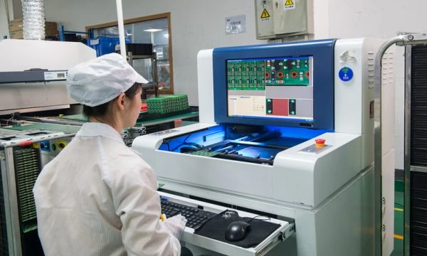
- AOI (Automated Optical Inspection): Checks for missing components, wrong polarity, or solder bridges. See AOI Inspection.
- ICT (In-Circuit Test): Uses a "bed of nails" fixture to verify the value of resistors and capacitors and check for shorts/opens on the bare board or assembled unit.
- FCT (Functional Circuit Test): The gold standard. The board is powered up, and a test rig simulates the entire filtration system, verifying that relays click when they should and sensor inputs read correctly. See FCT Test.
| Feature | Acceptance Criteria | Why it Matters |
|---|---|---|
| Solder Mask | No peeling, IPC-SM-840 Class H | Prevents moisture ingress under the mask. |
| Cleanliness | Ionic contamination < 1.56 µg/cm² NaCl eq. | Prevents electrochemical migration in humid air. |
| Coating | Uniform coverage, UV tracer verification | Ensures no gaps in environmental protection. |
| Burn-in | 24 hours @ 50°C, powered | Catches early component failures. |
The Future: Where This Is Going (Materials, Integration, Ai/automation)
The humble Filtration Control PCB is evolving. We are moving away from simple timer-based logic toward intelligent, data-driven systems. This shift impacts the PCB design, requiring more processing power, more memory, and better connectivity.
One major trend is the integration of Edge AI. Instead of just sending raw data to the cloud, the PCB itself analyzes sensor patterns to predict pump failure or optimize backwash cycles based on historical trends. This requires powerful microcontrollers or even small FPGAs, pushing the PCB technology towards higher density (HDI) and finer lines.
Another shift is in materials. As environmental regulations tighten, we see a move towards halogen-free laminates and lead-free solders that are not just compliant, but also robust enough for industrial use. The integration of wireless modules (Wi-Fi, LoRaWAN, NB-IoT) directly onto the main PCB—rather than as add-on cards—is becoming standard, requiring RF design expertise and impedance-controlled traces.
5-Year Performance Trajectory (Illustrative)
| Performance metric | Today (typical) | 5-year direction | Why it matters |
|---|---|---|---|
| **Connectivity** | Wired (Modbus/4-20mA) | Wireless Mesh / Edge AI | Enables predictive maintenance and remote monitoring without expensive cabling. |
| **Integration Level** | Discrete components | System-on-Module (SoM) | Reduces BOM count and assembly complexity while increasing processing power. |
| **Power Efficiency** | Linear regulation | High-efficiency GaN/SiC | Reduces heat generation in sealed enclosures, extending component life. |
Request a Quote / DFM Review for Filtration Control PCB (What to Send)
When you are ready to move from prototype to production with APTPCB, providing a complete data package ensures an accurate quote and a smooth manufacturing process. Because filtration boards often have special requirements (coating, heavy copper, specific impedance), ambiguity in the documentation can lead to delays.
To get the fastest response, please include the following details in your RFQ:
- Gerber Files: RS-274X format is preferred.
- Bill of Materials (BOM): Include manufacturer part numbers, especially for critical connectors and relays.
- Stackup Requirements: Specify if you need controlled impedance (e.g., 90Ω USB, 100Ω Ethernet).
- Copper Weight: Explicitly state if 2oz or heavier copper is required for power layers.
- Conformal Coating Specs: Type of coating (Acrylic, Silicone) and keep-out areas (connectors, test points).
- Testing Requirements: Do you need ICT, FCT, or burn-in? Providing a test procedure helps us estimate labor costs.
- Volume and Lead Time: Estimated annual usage (EAU) and batch sizes.
- IPC Class: Specify if IPC Class 2 (Standard) or Class 3 (High Reliability) is required.
For a detailed look at our quoting process, visit our Quote Page.
Conclusion
The Filtration Control PCB is a silent guardian in industrial and municipal infrastructure. Its design requires a careful balance of electrical precision, mechanical robustness, and chemical resistance. By understanding the environmental context—humidity, vibration, and noise—and selecting the right technologies (ENIG finish, proper isolation, conformal coating), engineers can ensure these boards survive the harsh reality of their service life.
Whether you are designing a compact controller for a medical dialysis machine or a rugged panel for a wastewater plant, the principles of reliability remain the same. Partnering with a manufacturer who understands these nuances is key to delivering a product that doesn't just work on the bench, but performs reliably in the field for years to come.