Contents
- The Context: What Makes Flex PCB Manufacturer Challenging
- The Core Technologies (What Actually Makes It Work)
- Ecosystem View: Related Boards / Interfaces / Manufacturing Steps
- Comparison: Common Options and What You Gain / Lose
- Reliability & Performance Pillars (Signal / Power / Thermal / Process Control)
- The Future: Where This Is Going (Materials, Integration, Ai/automation)
- Request a Quote / DFM Review for Flex PCB Manufacturer (What to Send)
- Conclusion
For APTPCB (APTPCB PCB Factory), a "good" flex PCB is defined by more than just electrical continuity. It represents a balance of mechanical endurance—surviving millions of flex cycles—and manufacturing yield. High-quality manufacturing ensures that coverlay openings align perfectly with pads and that impedance remains consistent despite the thin dielectric layers.
Highlights
- Material Science: The critical difference between adhesive-based and adhesiveless laminates for signal integrity and flexibility.
- Mechanical Reinforcement: How to correctly apply FR4, Polyimide, or Steel stiffeners without creating stress concentration points.
- Process Control: Managing the dimensional instability of polyimide during wet processing and high-temperature lamination.
- Dynamic vs. Static: Tailoring copper grain structure (Rolled Annealed vs. Electro-Deposited) to the application's movement profile.
The Context: What Makes Flex PCB Manufacturer Challenging
Flexible printed circuits (FPCs) introduce variables that do not exist in the rigid PCB world. The primary challenge is the material itself. Polyimide (PI) is hygroscopic and dimensionally unstable compared to FR4. It expands and contracts significantly during etching, plating, and lamination. A manufacturer must predict this movement and apply compensation factors to the artwork; otherwise, vias will not align with pads, and coverlay openings will shift.
Furthermore, the physical handling of materials as thin as 12µm or 25µm requires specialized transport systems. Standard conveyorized equipment used for rigid boards can tear or crumple thin flex sheets. Manufacturers must use leader boards or specialized frames to guide the flex through chemical baths.
Cost pressure often conflicts with reliability. Engineers may specify lower-cost adhesive-based laminates, but these adhesives can soften during reflow, leading to annular ring failure or Z-axis expansion issues. Understanding these trade-offs is the first step in successful procurement.
The Core Technologies (What Actually Makes It Work)
To produce a reliable flexible circuit, a manufacturer relies on several core technologies that differ from standard rigid fabrication.
Adhesiveless Copper Clad Laminates (FCCL): High-reliability applications now favor adhesiveless materials where copper is sputtered or cast directly onto the polyimide. This eliminates the acrylic adhesive layer, reducing thickness and improving thermal performance. It is essential for controlled impedance designs because the dielectric constant is more uniform.
- See more on Flex PCB Capabilities.
Coverlay Lamination: Instead of liquid solder mask, flex PCBs use "Coverlay"—a layer of polyimide with an adhesive backing. This is not printed; it is a solid sheet that must be pre-drilled or laser-cut and then aligned (registered) to the copper pattern. The lamination process requires precise pressure and temperature profiles to ensure the adhesive flows enough to seal the traces (encapsulation) but not so much that it bleeds onto the pads.
Laser Direct Imaging (LDI) and Laser Cutting: Mechanical routing induces stress and can leave burrs on soft polyimide. Advanced manufacturers use UV lasers for cutting the outline (profiling) and creating microvias. Laser cutting provides stress-free edges, which is critical for dynamic flex applications where edge micro-cracks can propagate into trace fractures.
Selective Plating: Flex boards often require soft gold or ENIG (Electroless Nickel Immersion Gold) for wire bonding or corrosion resistance. However, plating the entire panel can make the copper brittle. Manufacturers may use button plating or selective masking to keep the dynamic bend areas ductile while hardening the contact fingers.
- Explore PCB Material Options.
Ecosystem View: Related Boards / Interfaces / Manufacturing Steps
A flex PCB rarely exists in isolation. It is usually part of a larger electromechanical assembly.
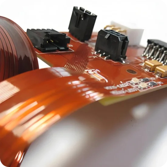
Rigid-Flex Integration: The natural evolution of flex is the Rigid-Flex PCB. Here, the flex layers penetrate the rigid sections, eliminating connectors entirely. This improves reliability but complicates manufacturing, as the manufacturer must manage two different material sets (FR4 and PI) with different thermal expansion rates in a single lamination cycle.
Assembly (PCBA) Considerations: For Flex and Rigid-Flex Assembly, the flexibility that is an asset in the final product becomes a liability during Surface Mount Technology (SMT) assembly. The flex circuit cannot support itself on a conveyor. It requires a dedicated carrier pallet or fixture to keep it flat during solder paste printing and component placement. If the manufacturer does not design these fixtures correctly, the board will warp during reflow, causing open joints or tombstoning.
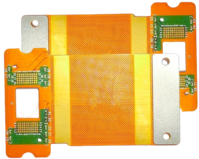
Connector Interfaces: Flex PCBs often terminate in ZIF (Zero Insertion Force) connectors. This requires precise control of the total thickness at the "fingers." Manufacturers must bond a stiffener (usually PI or FR4) under the contact area to meet the specific thickness tolerance of the connector (e.g., 0.3mm ±0.03mm).
Comparison: Common Options and What You Gain / Lose
When specifying a flex PCB, you face several binary choices. The material and structural decisions you make directly dictate the board's flexibility, thermal resistance, and cost.
Decision Matrix: Technical Choice → Practical Outcome
| Technical choice | Direct impact |
|---|---|
| Rolled Annealed (RA) vs. Electro-Deposited (ED) Copper | RA copper has a horizontal grain structure essential for dynamic flexing. ED copper is cheaper but prone to fatigue cracks in moving parts. |
| Adhesiveless vs. Adhesive-based Laminate | Adhesiveless allows for thinner boards, better dimensional stability, and higher temperature ratings. Adhesive-based is lower cost but thicker. |
| Polyimide (PI) vs. FR4 Stiffener | PI stiffeners are used to thicken ZIF contact areas slightly. FR4 stiffeners provide rigid support for heavy components or connectors. |
| Laser Profiling vs. Die Punching | Laser offers high precision and zero mechanical stress (good for prototypes/complex shapes). Die punching is faster and cheaper for high-volume simple shapes. |
Choosing the right Surface Finish is also critical. ENIG is standard, but for applications requiring extreme flexibility, OSP (Organic Solderability Preservative) or Immersion Tin might be preferred to avoid the brittle nature of nickel plating in the bend area.
Reliability & Performance Pillars (Signal / Power / Thermal / Process Control)
Reliability in flex PCBs is governed by mechanical integrity and electrical consistency.
Signal Integrity: Maintaining impedance on a flex board is difficult. The dielectric layers are very thin (often 1-2 mils), meaning trace widths must be narrow to achieve 50Ω or 100Ω impedance. A variation of just 0.5 mil in trace width can cause significant impedance mismatch. Manufacturers must use precise etching equipment and often employ "hatching" on ground planes to maintain flexibility while providing shielding.
Thermal Management: Polyimide has excellent thermal properties, but the adhesives used in coverlays do not. During lead-free reflow (260°C), moisture trapped in the polyimide can turn to steam and cause delamination (popcorning). Baking the flex boards before assembly is a mandatory Quality Control step.
Acceptance Criteria: A robust quality plan includes specific tests for flex circuits:
| Test Parameter | Typical Acceptance Criteria | Why it Matters |
|---|---|---|
| Peel Strength | > 0.8 N/mm (IPC-TM-650) | Ensures traces don't lift during soldering or bending. |
| Flexural Endurance | > 100,000 cycles (Dynamic) | Verifies the copper grain structure and stackup design. |
| Coverlay Registration | ± 0.15mm | Misalignment covers pads or exposes adjacent traces. |
| Dimensional Stability | < 0.1% shrinkage/expansion | Critical for connector alignment and automated assembly. |
The Future: Where This Is Going (Materials, Integration, Ai/automation)
The demand for wearables, foldable devices, and medical implants is pushing flex technology toward higher density and integration. We are moving away from simple "cables replacement" toward complex, multilayer logic boards that happen to be flexible.
5-Year Performance Trajectory (Illustrative)
| Performance metric | Today (typical) | 5-year direction | Why it matters |
|---|---|---|---|
| Min Trace/Space | 3mil / 3mil | < 1.5mil (mSAP) | Required for direct chip attachment and high-density interconnects in wearables. |
| Layer Count | 1-4 Layers | 6-10+ Layers (HDI) | Complex routing for smartphones and medical imaging sensors. |
| Via Technology | Mechanical / Laser Blind | Stacked Microvias / Any-Layer | Allows for extreme miniaturization and Z-axis routing flexibility. |
This evolution requires advanced HDI PCB techniques applied to flexible substrates, including semi-additive processes (mSAP) to achieve ultra-fine lines.
Request a Quote / DFM Review for Flex PCB Manufacturer (What to Send)
To get an accurate quote and a meaningful DFM review from APTPCB, your data package needs to be specific. Vague requirements lead to assumptions that can compromise flexibility.
- Gerber Files: Standard RS-274X format.
- Stiffener Drawings: Clearly mark locations and materials (FR4, PI, Steel) on a separate mechanical layer.
- Stackup Diagram: Specify total thickness, copper weight, and coverlay thickness.
- Application Type: State clearly if this is "Dynamic" (continuous motion) or "Static" (bend-to-install).
- Surface Finish: ENIG is standard, but specify if wire bonding is required.
- Impedance Requirements: List target ohms and reference layers.
- Quantity: Prototype vs. Mass Production affects the tooling method (Laser vs. Die).
- Bend Radius: If known, provide the minimum bend radius to verify material suitability.
Conclusion
Selecting a flex pcb manufacturer is a strategic decision that impacts the mechanical viability of your product. It requires navigating trade-offs between copper ductility, adhesive thermal limits, and manufacturing tolerances. A successful design is not just one that passes electrical test, but one that survives the physical reality of its application environment.
By engaging with the engineering team early—defining the bend radius, stiffener locations, and dynamic requirements—you can eliminate failure points before fabrication begins. Whether for a static sensor strip or a high-cycle robotic hinge, the right manufacturing process ensures your flexible circuit performs reliably for the life of the product.