
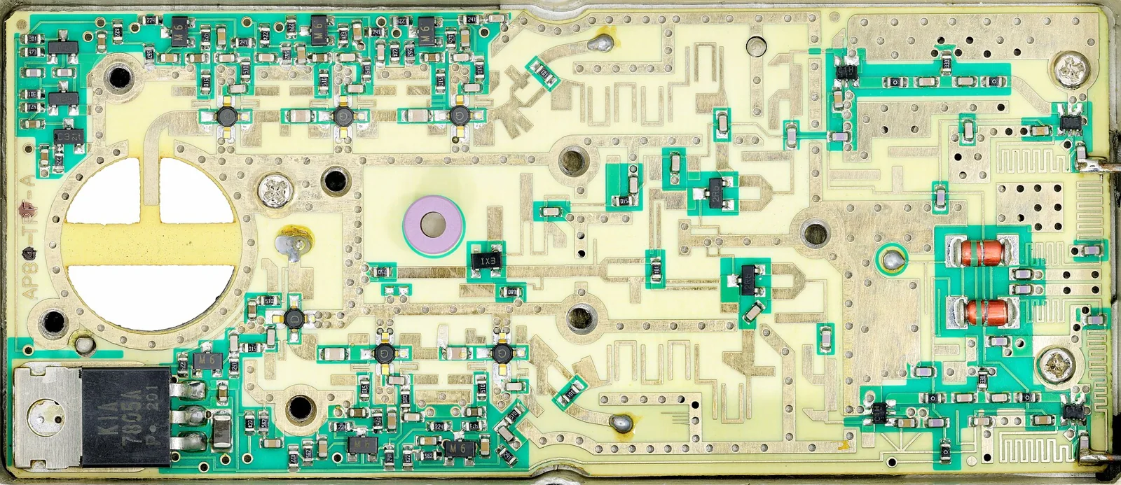
Choosing a high-frequency PCB manufacturer requires more than confirming that a supplier can process Rogers, PTFE, or other RF laminates. A qualified manufacturer must repeatedly transform a defined material system and stack-up into controlled RF geometry, plated structures, and measurable electrical performance.
The strongest supplier evidence comes from construction-specific process control: how the manufacturer models the stack-up, controls laminate processing, verifies impedance, measures RF performance, manages substitutions, and maintains traceability from material lot to finished board.
What should engineers evaluate when choosing a high-frequency PCB manufacturer?
A high-frequency PCB supplier should be evaluated across five technical areas:
- RF material processing capability
- stack-up and impedance ownership
- manufacturing process control
- electrical verification capability
- production traceability and change management
The manufacturer selection decision should be based on evidence that directly connects fabrication variables to RF performance.
High-frequency PCB manufacturer selection matrix
| Decision area | Strong evidence | Warning sign |
|---|---|---|
| Material processing | Documented recipe and qualification for exact material | One generic process for all RF laminates |
| Stack-up | Finished dimensions, copper and impedance jointly reviewed | Trace widths quoted before stack-up closure |
| Hole preparation | Resin/material-specific drilling and activation | Standard FR-4 hole process assumed |
| Etch control | Finished geometry capability tied to copper/material | Universal line-width tolerance |
| Impedance | Representative coupon, method and acceptance record | “Controlled impedance” without coupon definition |
| RF loss | Suitable S-parameter structure and de-embedding plan | TDR result presented as loss proof |
| Change control | Written approval before material/process substitution | “Equivalent” material substituted automatically |
| Traceability | Material lot, process and test records | Certificate logos without lot evidence |
How do you verify a high-frequency PCB manufacturer’s material expertise?
RF laminate experience must be specific to the selected construction. PTFE, ceramic-filled PTFE, hydrocarbon/ceramic laminates, and low-loss thermoset materials each require different fabrication controls.
A supplier should be able to explain how the selected material affects:
- storage, conditioning and handling;
- drilling parameters and tool-life control;
- plasma or chemical surface preparation;
- lamination pressure, temperature and cure behavior;
- multilayer registration;
- etch compensation and finished trace measurement;
- plated-hole reliability;
- surface finish compatibility.
For example, PTFE-based materials can require different drilling and bonding approaches than thermoset RF laminates. A manufacturer that understands the material family should explain the process decisions behind the board, not only list supported brands.
Specify the exact material whenever possible, including thickness and grade. Examples include Rogers RO4350B, RO4003C, or PTFE-based low-loss materials where applicable. The supplier should confirm availability, processing method, and any construction limitations before fabrication begins.
Who should own the RF PCB stack-up and impedance model?
The stack-up is one of the most important supplier qualification checkpoints because RF performance depends on the finished construction, not only the nominal laminate datasheet.
The manufacturer should review:
- dielectric thickness after lamination;
- copper weight and finished copper thickness;
- trace width after etching;
- copper profile and roughness considerations;
- layer-to-layer registration;
- impedance targets and tolerance requirements.
A reliable supplier does not calculate impedance from a generic material table alone. The model should represent the actual pressed construction and manufacturing process.
Ask:
- Which finished stack-up values are used in the impedance model?
- How are trace width and dielectric thickness measured?
- How does measured geometry feed back into process control?
- Which structures on the PCB are represented by the test coupon?
- How are impedance deviations handled during production?
How should impedance and RF loss testing be compared between PCB suppliers?
Controlled impedance and insertion loss are related but different measurements.
A coupon that passes impedance requirements demonstrates that the measured transmission line meets its target under the defined test method. It does not automatically prove that the complete RF path—including vias, launches, connectors, transitions, and long channels—meets the system loss budget.
A supplier qualification review should define:
| Parameter | Supplier evidence to request |
|---|---|
| Impedance | Coupon design, measurement method, acceptance window |
| Trace geometry | Finished line-width measurement and process capability data |
| Loss performance | Frequency range, S-parameter method, fixture and de-embedding approach |
| RF transitions | Via, connector, backdrill or launch validation where applicable |
| Electrical testing | Test report linked to board revision and material lot |
For demanding RF applications, ask whether the supplier can provide or support appropriate S-parameter testing structures. The measurement setup should match the frequency range and performance requirement of the design.
What manufacturing processes matter most for RF PCB reliability?
High-frequency PCB performance is created during fabrication. Important process controls include:
Lamination control
The supplier should demonstrate control of pressed dielectric thickness, resin flow, registration, and material compatibility in hybrid stack-ups.
Drilling and plated holes
RF structures can be sensitive to damaged hole walls, excessive roughness, poor activation, or inconsistent plating. Review drilling parameters, microsections, and plated-hole inspection methods.
Etching and finished geometry
RF impedance depends on finished trace dimensions. The supplier should understand how copper thickness, etch compensation, and conductor profile affect the final transmission line.
Surface finish and assembly compatibility
Surface finish selection should consider the electrical and assembly requirements of the application. The manufacturer should explain compatibility with the chosen laminate and operating environment.
How do certifications compare with real RF PCB evidence?
Certifications support quality-system requirements, but they do not replace project-specific validation.
A supplier may hold quality certifications while still requiring qualification for a specific RF construction.
Request relevant documentation, then review job-specific evidence:
- material certificate;
- approved stack-up;
- first article records;
- impedance results;
- RF test data where required;
- microsection results;
- electrical test records;
- approved deviations.
What questions should be included in an RF PCB manufacturer RFQ?
A technically complete RFQ allows manufacturers to provide comparable commitments.
Include:
- application and frequency band;
- loss, impedance, return-loss, phase and power requirements;
- exact material preference or approved material decision process;
- stack-up information;
- RF-critical traces, vias, connectors and transitions;
- fabrication drawings;
- drill files and mechanical requirements;
- copper profile requirements;
- surface finish requirements;
- coupon and test requirements;
- quantity, panelization and production forecast;
- traceability and substitution requirements.
How should a first build be used to qualify an RF PCB supplier?
A trial build should verify both the design package and the manufacturer’s process capability.
Review:
- DFM and stack-up closure before release;
- controlled fabrication data revision;
- finished dielectric thickness;
- critical trace dimensions;
- plated-hole microsections;
- impedance measurements;
- RF test structures where applicable;
- material lot records;
- manufacturing exceptions and corrective actions.
The goal is to confirm that simulation assumptions, fabrication results, and measured electrical behavior are aligned before volume production.
High-frequency PCB manufacturer qualification checklist
Use this checklist when comparing suppliers:
- Exact RF laminate family and thickness confirmed
- Manufacturer reviewed finished stack-up requirements
- Impedance model based on actual construction
- Coupon structures defined before production
- TDR method and acceptance limits documented
- S-parameter testing requirements reviewed when needed
- Material lots and production records traceable
- Process substitutions require approval
- First article acceptance criteria documented
- RF-critical structures reviewed with engineering support
Evaluate high-frequency PCB fabrication, microwave PCB and testing and quality, then submit the controlled package through the PCB quotation page.
Standards and references
- IPC-6018 — Qualification and performance for high-frequency printed boards
- IPC-4103 — Base materials for high-speed/high-frequency applications
- IPC-2141 — Controlled impedance circuit boards and high-speed logic design
- IPC-2221 — Generic printed board design
- IPC-TM-650 — Printed-board test methods
- ISO 9001 — Quality management systems
Confirm current editions and the supplier's actual certification scope.
High-frequency PCB manufacturer FAQ
What is the fastest way to screen an RF PCB supplier?
Ask for construction-specific evidence: material processing experience, stack-up ownership, impedance validation, testing capability, and change-control procedures.
Does a broad RF material list prove manufacturing capability?
No. Confirm experience with the exact laminate family, thickness, copper configuration, and multilayer construction required by the project.
Is a passing impedance coupon enough for an RF design?
No. Impedance testing validates the measured coupon structure. Complete RF performance may also depend on vias, launches, connectors, transitions, and channel loss.
Should the lowest RF PCB quote win?
Compare what each supplier includes: material assumptions, stack-up review, coupons, testing, reports, first article requirements, tooling, and change control.
What should happen when the specified laminate is unavailable?
The supplier should request approval with technical comparison and explain the impact on impedance, loss, fabrication, and qualification requirements. Material substitution should not occur automatically.