A high-speed ECG acquisition board represents the intersection of precision analog engineering and robust digital processing. While the fundamental cardiac signal ranges from 0.05 Hz to 150 Hz, modern diagnostic requirements demand much higher performance. "High-speed" in this context refers to high sampling rates (often 32 kHz or higher) required for pacemaker pulse detection, high-resolution late potential analysis, and the rapid digital transmission of multi-channel data to host processors. Designing and assembling these boards requires strict adherence to medical safety standards (IEC 60601), exceptional signal integrity, and rigorous noise management.
APTPCB (APTPCB PCB Factory) specializes in the manufacturing of high-reliability medical electronics, ensuring that the stringent requirements for isolation, cleanliness, and impedance control are met during production. This guide provides engineers with a comprehensive technical framework for developing, troubleshooting, and manufacturing a high-speed ECG acquisition board.
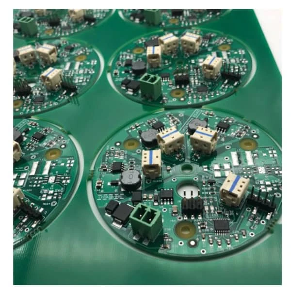
high-speed ECG acquisition board quick answer (30 seconds)
- Sampling Rate Criticality: High-speed acquisition (≥32 kSPS) is essential for detecting narrow pacemaker pulses (often <2 ms width) which standard 500 Hz sampling misses.
- Isolation is Non-Negotiable: You must maintain strict creepage and clearance distances (typically ≥8mm for mains isolation) between the patient side (Applied Part) and the digital/power side.
- Analog-Digital Partitioning: Never route high-speed digital traces (SPI, USB, LVDS) under sensitive analog front-end (AFE) components; use separate ground planes joined at a single point (ADC or isolator).
- Impedance Control: While ECG signals are low frequency, the digital interface carrying the data is high-speed; unmatched impedance here causes reflections that radiate noise into the high-impedance analog inputs.
- Cleanliness Matters: Flux residue on a PCB creates parasitic resistance. For ECG circuits with input impedances >10 MΩ, this leakage causes DC baseline drift and noise.
- Power Supply Rejection: Use low-noise LDOs for the analog section. Switch-mode power supplies (SMPS) must be synchronized or filtered heavily to prevent switching noise from aliasing into the ECG passband.
When high-speed ECG acquisition board applies (and when it doesn’t)
Understanding the specific use case ensures you do not over-engineer a simple heart rate monitor or under-engineer a clinical diagnostic tool.
When high-speed ECG acquisition board applies
- Clinical 12-Lead Diagnostics: Systems requiring simultaneous sampling of all leads with high dynamic range to detect minute ST-segment changes.
- Pacemaker Pulse Detection: Devices that must identify and reject artificial pacing artifacts, requiring high-bandwidth analog channels and fast sampling.
- High-Resolution Holter Monitors: Portable units that record raw data for 24+ hours, requiring efficient high-speed writing to storage without corrupting the analog signal.
- Stress Test Systems: Equipment operating in high-motion environments where rapid baseline recovery and advanced digital filtering (DSP) are necessary.
- Research & Signal Analysis: Applications analyzing "late potentials" (high-frequency, low-amplitude signals at the end of the QRS complex).
When high-speed ECG acquisition board does not apply
- Basic Fitness Trackers: Wearables that only calculate beats per minute (BPM) typically use photoplethysmography (PPG) or simplified single-lead ECG with low sampling rates.
- Event Recorders (Loop Recorders): Devices that only capture a few seconds of data upon activation often prioritize battery life over high-speed acquisition fidelity.
- Educational Kits: Simple DIY ECG modules using basic op-amps generally lack the safety isolation and bandwidth required for "high-speed" classification.
- Standard Bedside Monitors: While medical-grade, basic monitors focused only on heart rate and basic rhythm may not require the ultra-high sampling rates of diagnostic-grade acquisition boards.
high-speed ECG acquisition board rules and specifications (key parameters and limits)
The following table outlines the critical parameters for a high-speed ECG acquisition board. Adhering to these rules ensures signal fidelity and patient safety.
| Rule | Recommended Value/Range | Why it matters | How to verify | If ignored |
|---|---|---|---|---|
| Input Impedance | > 10 MΩ (DC); > 500 MΩ preferred | High skin-electrode impedance forms a voltage divider. Low board impedance attenuates the signal. | Electrometer or Source Measure Unit (SMU). | Signal amplitude loss; severe baseline wander due to electrode mismatch. |
| CMRR (Common Mode Rejection) | > 100 dB (at 50/60 Hz) | The body acts as an antenna for mains hum. The board must reject this common-mode noise. | Inject common mode signal, measure differential output. | 50/60 Hz noise swamps the ECG signal, making it unreadable. |
| Sampling Rate | 500 SPS (Standard) to 32 kSPS (Pacing) | High rates capture fast transients like pacemaker spikes. | Frequency counter on ADC "Data Ready" pin. | Missed pacemaker spikes; aliasing of high-frequency noise. |
| ADC Resolution | 24-bit (Sigma-Delta) | ECG signals have a large DC offset (300mV) but small AC signal (1mV). High dynamic range is needed. | Histogram test with shorted inputs. | Inability to resolve P-waves in the presence of electrode offset voltage. |
| Creepage Distance | ≥ 8 mm (Mains to Patient) | Prevents high voltage arcing across the PCB surface, ensuring patient safety (IEC 60601-1). | Calipers or CAD clearance check rules. | Failed safety certification; risk of electric shock to patient. |
| PCB Material CTI | CTI ≥ 175V (FR4), Pref ≥ 400V (Group II) | Comparative Tracking Index determines how easily the material conducts under stress/contamination. | Material datasheet verification (IPC-4101). | Larger creepage distances required; potential carbonization tracks over time. |
| Trace Width (Power) | Calculated for < 10°C rise | Digital processing for high-speed acquisition consumes power; voltage drops affect ADC reference. | IR thermal camera during operation. | Vref instability causing measurement errors; localized heating. |
| Analog/Digital Split | 100% Separation | Digital switching noise couples into high-impedance analog lines via parasitic capacitance. | Visual inspection of Gerber files (Layer 2/3). | High-frequency digital hash visible on the ECG baseline. |
| Defibrillation Protection | Series Resistors + Gas Discharge Tubes | The board must survive 5kV pulses from a defibrillator. | Dielectric withstand test (Hi-Pot) with limited energy. | Board destruction during emergency defibrillation; component explosion. |
| Input Bias Current | < 500 pA | Bias current charges the electrode capacitance, causing DC drift. | Picoammeter measurement at input pins. | Rapid saturation of the amplifier chain; constant baseline drift. |
high-speed ECG acquisition board implementation steps (process checkpoints)

Designing and building a high-speed ECG acquisition board requires a disciplined workflow. Each step builds upon the previous one to ensure the final PCBA meets medical and technical standards.
Architecture & AFE Selection
- Action: Choose a specialized Analog Front End (AFE) IC or discrete instrumentation amplifier. For high-speed applications, integrated AFEs with built-in pacemaker detection and 24-bit ADCs are preferred.
- Key Parameter: Input referred noise (< 10 µVpp).
- Acceptance Check: Verify the component availability and lifecycle (medical products have long lifecycles).
Stackup Definition
- Action: Define a 4-layer or 6-layer stackup. Use internal planes for shielding.
- Key Parameter: Layer order: Signal - Ground - Power - Signal.
- Acceptance Check: Ensure the distance between the signal layer and reference plane is minimized for impedance control of digital lines. Refer to multilayer PCB guidelines for optimal arrangements.
Schematic Design & Isolation Strategy
- Action: Place the isolation barrier (digital isolators + isolated DC-DC converter) between the MCU/USB interface and the AFE.
- Key Parameter: Isolation rating (e.g., 5kVrms).
- Acceptance Check: Review netlist to ensure no copper nets cross the isolation gap inadvertently.
Layout: Component Placement
- Action: Place analog components as close to the input connectors as possible. Group digital components at the opposite end.
- Key Parameter: Signal path length.
- Acceptance Check: Verify that the "keep-out" zone in the isolation gap is free of components and copper pours.
Routing: Analog & Digital
- Action: Route analog inputs as differential pairs to maximize noise rejection. Route high-speed digital lines (SPI/LVDS) with controlled impedance.
- Key Parameter: Differential impedance (usually 100Ω).
- Acceptance Check: Run DRC (Design Rule Check) for crosstalk and length matching.
Power Integrity Analysis
- Action: Place decoupling capacitors immediately at power pins. Use ferrite beads to filter analog power rails (AVDD).
- Key Parameter: PSRR (Power Supply Rejection Ratio) at switching frequency.
- Acceptance Check: Simulate PDN (Power Delivery Network) impedance or verify with a spectrum analyzer on a prototype.
Fabrication & Assembly (DFM)
- Action: Submit data for manufacturing. Specify strict cleanliness requirements (ionic contamination test).
- Key Parameter: Solder mask expansion and surface finish (ENIG is preferred for flatness).
- Acceptance Check: Confirm the manufacturer can handle the specific medical PCB cleanliness standards.
Functional Testing & Calibration
- Action: Use an ECG simulator to inject known signals (sine waves, ECG waveforms).
- Key Parameter: Signal-to-Noise Ratio (SNR).
- Acceptance Check: Output waveform matches simulator input with <1% distortion; noise floor is within spec.
high-speed ECG acquisition board troubleshooting (failure modes and fixes)
Even with a perfect design, issues can arise during the prototype phase. This section maps common symptoms to their root causes and fixes.
1. Symptom: Excessive 50/60 Hz Mains Hum
- Causes: Poor CMRR, unshielded cables, floating ground, or "Right Leg Drive" (RLD) circuit failure.
- Checks: Verify the RLD amplifier is driving the patient reference correctly. Check for ground loops in the test setup.
- Fix: Increase RLD gain (within stability limits). Use shielded electrode cables.
- Prevention: Implement a robust RLD circuit and ensure tight matching of input protection resistors.
2. Symptom: Wandering Baseline (Low Frequency Drift)
- Causes: Electrode polarization, high input bias current, or dirty PCB surface (flux residue).
- Checks: Measure input bias current. Inspect PCB under UV light for flux residues.
- Fix: Clean the PCBA thoroughly using ultrasonic cleaning. Switch to AC-coupled inputs if DC tracking isn't required (though DC is preferred for ST analysis).
- Prevention: Specify "No-Clean" flux or rigorous wash processes during turnkey assembly.
3. Symptom: High-Frequency "Fuzz" on Signal
- Causes: Digital switching noise coupling, aliasing, or SMPS ripple.
- Checks: Probe the analog power rail (AVDD). Look for correlation between noise spikes and digital clock edges.
- Fix: Add RC snubbers to digital lines. Improve filtering on LDO inputs.
- Prevention: strict physical separation of analog and digital grounds; use of solid reference planes.
4. Symptom: Signal Saturation (Rail-to-Rail)
- Causes: Electrode offset voltage exceeds amplifier dynamic range; ESD damage to input.
- Checks: Measure DC voltage at amplifier inputs. Check for shorted protection diodes.
- Fix: Replace damaged input protection components. Reduce gain of the first stage.
- Prevention: Use high-voltage tolerant input protection and ensure gain distribution allows for ±300mV DC offsets.
5. Symptom: Missing Pacemaker Spikes
- Causes: Sampling rate too low, analog bandwidth too narrow, or digital filter too aggressive.
- Checks: Verify ADC sampling rate is ≥32 kSPS (or specialized hardware pace detection is enabled). Check anti-aliasing filter cutoff.
- Fix: Bypass heavy digital filtering for the pace detection channel. Increase analog bandwidth.
- Prevention: Design a dedicated high-bandwidth path for pace detection parallel to the ECG path.
How to choose high-speed ECG acquisition board (design decisions and trade-offs)
Successful execution of a high-speed ECG acquisition board relies on making the right trade-offs early in the design phase.
ADC Architecture: SAR vs. Delta-Sigma For high-speed ECG, Delta-Sigma (ΔΣ) ADCs are generally preferred. They offer massive oversampling capabilities which simplify anti-aliasing filter requirements and provide high resolution (24-bit). While SAR ADCs are faster, the resolution and noise performance of ΔΣ converters are superior for the small dynamic range of bio-potentials.
PCB Surface Finish ENIG (Electroless Nickel Immersion Gold) is the standard for medical boards. It provides a flat surface for fine-pitch components (like AFEs and BGAs) and offers excellent corrosion resistance. HASL (Hot Air Solder Leveling) is generally avoided due to uneven surfaces and the potential for micro-shorts on fine-pitch devices.
Connector Selection The interface to the patient cable is a critical failure point. Connectors must be robust (high mating cycles) and provide shielding. Plastic medical connectors with keyed inserts are standard to prevent accidental connection to non-isolated equipment.
Rigid vs. Rigid-Flex For compact Holter monitors or patch-based ECGs, rigid-flex PCB technology is invaluable. It eliminates bulky connectors between the sensor board and the main processor board, reducing noise and improving reliability in high-vibration environments.
high-speed ECG acquisition board FAQ (cost, lead time, Fabrication & Assembly (DFM) files, stackup, impedance, for aesthetic reasons in medical devices but can make automated optical inspection (AOI) inspection)
Q: Why do I need "high-speed" for a 1 Hz heart signal? A: While the heart rate is low, the QRS complex has high-frequency components. More importantly, detecting pacemaker pulses (which can be as short as 0.5ms) requires high sampling rates (32kHz+) to ensure the pulse is not missed between samples.
Q: Can I use a standard FR4 material for this board? A: Yes, standard FR4 is sufficient for the signal frequencies involved. However, ensure the material has a high Comparative Tracking Index (CTI) if you are designing for high voltage safety compliance. For the high-speed digital interface section, standard FR4 is usually acceptable unless trace lengths are very long.
Q: How do I handle the ground plane? A: Do not split the ground plane under the AFE if possible. Instead, use a "split" layout where analog components are on one side and digital on the other, with a solid ground plane underneath that is physically separated only at the isolation barrier.
Q: What is the role of the Right Leg Drive (RLD)? A: The RLD actively cancels common-mode noise (like 50/60Hz hum) by inverting the common-mode signal and driving it back into the patient's body (usually via the right leg electrode).
Q: How do I test for IEC 60601 compliance during prototyping? A: You cannot do full certification, but you can perform pre-compliance tests: measure leakage current, verify dielectric strength (Hi-Pot) of the isolation barrier, and measure creepage/clearance distances on the physical board.
Q: What is the best way to protect inputs from defibrillation? A: Use a combination of pulse-withstanding resistors (to limit current) and gas discharge tubes or neon bulbs (to shunt high voltage). TVS diodes alone often cannot handle the energy of a defibrillation pulse.
Q: Does the PCB color matter? A: Technically no, but Green or Blue is standard. White is sometimes used for aesthetic reasons in medical devices but can make automated optical inspection (AOI) slightly more difficult due to lower contrast.
Q: How does flux residue affect ECG signals? A: Flux is weakly conductive. On high-impedance ECG lines, it creates a parallel resistance that varies with humidity, causing unpredictable DC drift and noise.
Q: What data format is used for high-speed ECG? A: Raw data is often streamed via SPI or I2S to a microcontroller. The MCU then packets this data (often compressing it) for transmission via USB or Wireless.
Q: Can I use wireless transmission directly from the acquisition board? A: Yes, but the radio module (Bluetooth/Wi-Fi) introduces significant RF noise. Shielding and careful layout are required to prevent RF rectification in the analog front end.
high-speed ECG acquisition board glossary (key terms)
| Term | Definition |
|---|---|
| AFE (Analog Front End) | The integrated circuit or discrete section that amplifies, filters, and digitizes the raw analog signal from the electrodes. |
| Artifact | Any signal component that is not generated by the heart (e.g., muscle noise, motion, mains hum). |
| Creepage | The shortest distance between two conductive parts along the surface of the solid insulating material. Critical for safety. |
| Clearance | The shortest distance between two conductive parts through the air. |
| CMRR | Common Mode Rejection Ratio; the ability of the amplifier to reject signals common to both inputs (like mains noise). |
| Defibrillation Protection | Circuitry designed to protect the ECG board from high-voltage shocks applied to the patient during resuscitation. |
| Holter Monitor | A portable device for continuously monitoring various electrical activity of the cardiovascular system for at least 24 hours. |
| Isolation Barrier | A physical and electrical gap on the PCB that separates the patient-connected circuitry from the mains-powered or non-medical circuitry. |
| Pacemaker Spike | A very short, high-amplitude electrical pulse generated by an artificial pacemaker to stimulate the heart. |
| Wilson Central Terminal (WCT) | A reference potential generated by averaging the signals from the Right Arm, Left Arm, and Left Leg electrodes. |
| Late Potentials | High-frequency, low-amplitude signals at the end of the QRS complex, requiring high-resolution acquisition to detect. |
| Lead-off Detection | A feature that detects if an electrode has disconnected from the patient, usually by monitoring impedance or DC levels. |
Request a quote for high-speed ECG acquisition board (Fabrication & Assembly (DFM) review + pricing)
For medical-grade electronics, precision in manufacturing is as critical as the design itself. APTPCB provides comprehensive DFM reviews to ensure your high-speed ECG acquisition board meets strict impedance, cleanliness, and safety requirements before production begins.
To get an accurate quote and DFM analysis, please prepare:
- Gerber Files: RS-274X format with all layers clearly labeled.
- Stackup Diagram: Specifying material types (e.g., High-CTI FR4), layer thickness, and impedance requirements.
- BOM (Bill of Materials): Including specific part numbers for critical isolation and AFE components.
- Assembly Notes: Highlighting cleanliness requirements (ionic contamination limits) and testing procedures.
- Volume: Prototype quantity vs. expected mass production volume.
Conclusion (next steps)
Developing a high-speed ECG acquisition board is a complex balance of capturing microvolt-level biological signals while rejecting aggressive environmental noise and ensuring absolute patient safety. By adhering to strict isolation rules, optimizing the PCB stackup for signal integrity, and selecting the right manufacturing partner, engineers can deliver diagnostic-grade performance. APTPCB stands ready to support your medical device development with advanced fabrication and assembly services tailored for high-reliability applications.