When you push LEDs into the 1W, 5W, 10W and above range, thermal management stops being a detail and becomes the design constraint.
Same LED, same driver, same optics—yet one module runs cool for years while another fails early, drifts in color, or cannot pass reliability testing.
The difference is often in one place:
how well the LED MCPCB is designed and manufactured to move heat away from the LED junction.
A standard FR-4 PCB with ~0.2–0.5 W/m·K thermal conductivity simply cannot keep up with modern high-power LEDs. That’s why metal core PCBs (MCPCB)—especially LED aluminum MCPCBs—have become the default platform for serious lighting, automotive, industrial and UV applications.
At APTPCB, we design and manufacture metal core PCBs and high-thermal solutions for LED customers worldwide. This guide is written for hardware engineers, thermal engineers and product owners who want practical guidance on LED MCPCB selection, stack-up, and manufacturing—not just theory.
On This Page
- Why LED MCPCB Matters for High-Power LED Design
- LED MCPCB Stack-Up and Heat Path Basics
- Key Design Decisions for LED MCPCB Performance
- Advanced LED MCPCB Structures and When to Use Them
- How APTPCB Manufactures Reliable LED MCPCBs
- Testing and Validating LED MCPCB Performance
- Working with APTPCB on Your Next LED MCPCB
Why LED why metal core PCBs (MCPCB) Matters for High-Power LED Design
For low-power indicator LEDs on FR-4, thermal issues are usually manageable with copper pours and a decent enclosure. For high-power LED modules, it’s different:
- Junction temperature (Tj) controls lumen output, color stability and lifetime.
- Heat must travel through the package, solder, PCB and housing to ambient.
- Any bottleneck—especially in the PCB—shows up as hotspots and early failures.
A typical pain pattern we see before customers move to a proper LED MCPCB:
- Prototype passes basic functional tests but fails thermal or reliability testing.
- Luminaire meets brightness spec in the lab, but drops quickly in the field.
- Multiple heatsink iterations with little improvement because the bottleneck is inside the PCB, not outside.
That’s exactly where an LED MCPCB adds value. Compared to FR-4, a properly designed metal core PCB:
- Reduces thermal resistance between LED pad and heatsink
- Keeps junction temperatures lower at the same power level
- Enables higher power density or smaller heatsinks for the same lifetime
If your design includes:
- High-power LED emitters or COBs
- Compact, thermally constrained housings
- Outdoor, automotive, industrial or UV applications
Then starting from an LED MCPCB stack-up, instead of a generic FR-4 board, will usually save you time, re-spins and thermal debugging.
LED why metal core PCBs (MCPCB) Stack-Up and Heat Path Basics
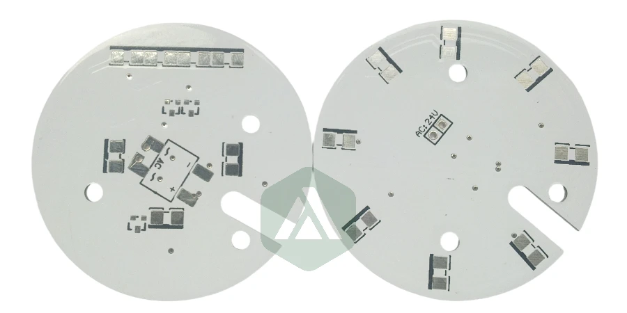
Most LED MCPCBs used in lighting are single-layer metal core PCBs with a simple but critical stack-up:
Copper Circuit Layer (1–3 oz or thicker)
- Carries current and acts as the first heat spreader.
- Land pattern and copper area under and around the LED strongly influence local temperature.
Thermally Conductive Dielectric Layer
- Thin (typically 50–150 μm) insulating layer with much higher thermal conductivity than FR-4.
- Transfers heat vertically from copper into the metal core.
- Thermal conductivity (k) usually in the 1–8 W/m·K range, versus ~0.3 W/m·K for FR-4.
Metal Core (usually aluminum, sometimes copper)
- Acts as a built-in heat spreader and mechanical backbone.
- Aluminum cores typically offer ~180–220 W/m·K; copper even higher but heavier and more expensive.
- Thickness commonly 1.0–3.0 mm depending on stiffness and thermal needs.
From a thermal point of view, the path looks like a series of resistances:
LED junction → LED package → solder → copper pad → dielectric → metal core → heatsink/housing → ambient
In many real designs, the dielectric layer is the dominant PCB bottleneck:
- If it is too thick or has low thermal conductivity, junction temperatures rise quickly.
- If it’s thin and has high k, the Rθ across the PCB drops sharply, giving the heatsink a real chance to work.
At APTPCB, we start LED MCPCB discussions with stack-up and heat path, not just copper thickness or outline.
Key Design Decisions for LED why metal core PCBs (MCPCB) Performance
Designing a good LED MCPCB is mostly about making a few key decisions correctly and ensuring they are manufacturable at scale.
1. Choosing the Right Dielectric System
The dielectric is the heart of LED MCPCB thermal management and must balance:
Thermal conductivity (k):
- FR-4: ~0.2–0.5 W/m·K
- LED MCPCB dielectric: 1.0–8.0+ W/m·K
- Higher k → lower thermal resistance for the same thickness.
Electrical insulation and breakdown voltage:
- Must safely isolate circuit copper from the metal core, especially for mains or high-voltage drivers.
Thickness and uniformity:
- Thinner = better for thermal performance, but manufacturing consistency is critical to avoid hot spots.
For different power densities and applications, we can recommend suitable dielectric families from our high-thermal PCB and metal core material portfolio.
2. Selecting Aluminum vs Copper Core (and Thickness)
Aluminum MCPCB
- Standard choice for most LED lighting, automotive and industrial projects.
- Good balance of thermal performance, weight and cost.
Copper core MCPCB
- Used in extreme power densities or very compact modules.
- Offers the highest thermal conductivity but at higher cost and weight.
Key trade-offs:
- Required thermal performance (junction temp targets)
- Mechanical stiffness and flatness
- Size and weight limits
- Cost sensitivity
3. Copper Weight, Layout and Pad Design
The copper layer is both the electrical network and lateral heat spreader:
- Heavier copper (2 oz, 3 oz and above) helps spread heat, especially in multi-chip LED arrays.
- Pad design on LED thermal pads (solid vs segmented) affects voiding and mechanical stress.
- Wider traces and copper pours around high-power LEDs reduce local temperature rise.
We use our advanced PCB manufacturing capability to combine heavy copper with fine features where needed.
4. Solder Mask Color and Surface Finish
For many LED modules, white solder mask is preferred to boost reflectivity. In other designs, black or custom colors are used to control glare or match industrial design.
- We help you choose solder mask and finish combinations that stay color-stable under reflow and operating temperatures.
- Surface finishes (ENIG, OSP, etc.) are selected based on reliability, assembly process, and cost.
Advanced LED why metal core PCBs (MCPCB) Structures and When to Use Them
Not all LED designs fit into a simple single-layer MCPCB. For more demanding products, different MCPCB stackup examples and structures can be used.
Multi-Layer MCPCB
When you need:
- More complex routing (e.g., integrated drivers or signal lines)
- Compact, high-function LED modules
we can add additional FR-4 or high-Tg layers on top of the metal core, creating a hybrid multi-layer laminated structure. Heat must then travel through more layers, so we treat thermal design and stack-up engineering very carefully.
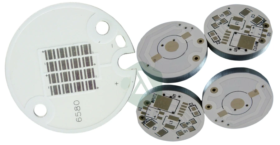
Copper Coins / Inlays for Extreme Hotspots
For very high-power LEDs or UV sources, embedding solid copper coins or slugs directly under the LED:
- Creates an ultra-low thermal resistance path from LED pad to metal core or heatsink.
- Requires precise machining and lamination control.
APTPCB routinely implements these embedded copper solutions in high-power modules where every degree counts.
Hybrid FR-4 + MCPCB Designs
A common architecture:
- MCPCB for the LED engine
- FR-4 for driver and control boards, linked via connectors or flex
As a full PCB factory, we can build and coordinate both sides and, if needed, supply them as a matched set.
Rigid-Flex + MCPCB
In applications where you want a thin, flexible connection to a high-thermal LED engine (e.g., automotive, wearables, compact luminaires):
- MCPCB is used for the LED head
- Flex or rigid-flex handles wiring and mechanics
We manufacture both flex/rigid-flex and MCPCB in-house, avoiding cross-factory compatibility issues.
How APTPCB Manufactures Reliable LED MCPCBs
The best LED MCPCB design still needs a factory that can hold tight process windows on real production lines.
At APTPCB, LED MCPCB production is built on our standard PCB fabrication process, adapted for metal cores and high-thermal dielectrics:
- Controlled lamination of thermally conductive dielectric to aluminum / copper cores
- Precise copper etching, even on heavy copper layers
- Tight control of dielectric thickness and uniformity across the panel
- Specialized drilling, routing and deburring for metal cores
- Flatness control for large LED panels and modules
Because LED MCPCB is part of our broader metal core PCB offering, it benefits from the same tooling, process control and engineering experience we use for power, automotive and industrial customers.
If you need PCB + assembly, our turnkey PCB assembly services can also handle LED placement, drivers, sensors and full module build in one flow.
Testing and Validating LED why metal core PCBs (MCPCB) Performance
For high-power LED modules, “looks good” is not a test plan. We validate LED MCPCBs using a mix of thermal, electrical and mechanical checks, integrated into our overall PCB quality system.
Key thermal and electrical checks include:
Dielectric thermal conductivity and thermal resistance
- Material-level tests and, where needed, board-level thermal impedance measurements.
Dielectric breakdown and insulation
- Hi-pot tests for safety and insulation integrity between copper and metal core.
Flatness and warpage
- Essential for proper heatsink contact and LED placement.
Cross-section analysis
- To verify dielectric thickness, adhesion, absence of voids, and copper etch quality.
For customers who need it, we can support:
- Thermal cycling of sample boards
- Burn-in or elevated temperature operation tests
- Application-level verification on assembled LED modules
Working with APTPCB on Your Next LED why metal core PCBs (MCPCB)
The best results come when we are involved early enough to influence stack-up and materials—not just “build whatever is in the Gerber”.
For a new LED MCPCB thermal management project, it helps if you can share:
- Target LED type and power (e.g., 10 x 3 W LEDs, 50 W COB, UV LED array)
- Board size, shape, and mechanical constraints
- Target ambient and maximum allowed case/junction temperature
- Planned heatsink or housing concept (if any)
- Electrical requirements (voltage, creepage/clearance needs, safety standards)
- Lifetime and reliability expectations (hours, environment, certifications)
From there, our engineering team can:
- Recommend a suitable MCPCB stack-up and dielectric system
- Suggest aluminum vs copper core and thickness
- Advise on copper weight, layout and panelization
- Provide a manufacturing-feasible DFM review before you lock the design
If you’re working on a high-power LED module—whether for lighting, automotive, industrial, UV or display backlighting—APTPCB can serve as both your LED MCPCB designer and manufacturer, helping you turn thermal bottlenecks into a competitive advantage instead of a headache.