
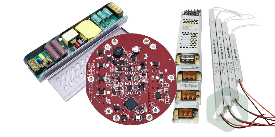
LED products depend on more than LED chips and optical design. The PCB determines how efficiently heat leaves the LED junction, how reliably current is delivered, and how consistently the product performs throughout its lifetime.
A poorly matched PCB material, uncontrolled assembly process, or incomplete test strategy can lead to:
- brightness degradation
- color shift between LED units
- solder joint failures
- driver overheating
- premature product returns
Selecting the right LED PCB manufacturing partner requires understanding both the circuit board technology and the production controls behind it.
APTPCB provides LED PCB fabrication and assembly services covering:
- FR-4 and high-Tg LED control boards
- aluminum and copper MCPCBs
- ceramic LED substrates
- SMT, through-hole, and mixed-technology assembly
- LED driver and control electronics
- inspection and functional testing
This guide explains the engineering decisions that influence LED PCB reliability and how to evaluate a manufacturing partner.
How Do You Choose the Right LED PCB Material?
The correct PCB material depends on LED power density, thermal requirements, mechanical design, and cost targets. There is no single LED PCB technology that fits every application.
LED PCB Material Selection Matrix
| PCB Type | Best Applications | Thermal Capability | Main Advantages | Design Considerations |
|---|---|---|---|---|
| FR-4 | Indicators, displays, control boards, low/medium power lighting | Moderate with thermal vias and copper planes | Cost-effective, widely available, supports complex circuits | Requires careful heat path design for higher power LEDs |
| Aluminum MCPCB | LED modules, commercial lighting, automotive lighting | High thermal dissipation through metal core | Excellent heat spreading, lightweight, cost-effective | Requires controlled dielectric thickness and lamination quality |
| Copper-Core PCB | High-power lighting, demanding thermal environments | Very high heat transfer capability | Maximum thermal performance | Higher cost and more complex fabrication |
| Ceramic PCB | COB, automotive, medical, extreme-temperature applications | Excellent thermal conductivity and CTE stability | Reliable at high temperature and high power density | Higher material cost and specialized processing |
For many LED products, multiple PCB technologies work together. An LED engine may use MCPCB or ceramic material while the driver and communication electronics use FR-4.
APTPCB supports these combinations under one manufacturing workflow, allowing LED modules, drivers, and control electronics to be produced with consistent engineering coordination.
What PCB Design Factors Determine LED Reliability?
LED PCB manufacturing is fundamentally a thermal and electrical design challenge. The PCB must move heat away from the LED while maintaining stable current delivery.
Important design factors include:
Thermal Management
High-power LEDs generate significant heat at the semiconductor junction. The PCB design must provide a low-resistance thermal path through:
- aluminum or copper cores
- thermal vias
- heavy copper layers
- optimized thermal pads
- mechanical heatsink interfaces
For FR-4 LED boards, thermal vias under LED packages can transfer heat toward internal copper planes or external heat spreaders.
Copper Thickness and Current Capacity
Copper weight affects both electrical performance and heat spreading.
Higher copper weights can improve:
- current-carrying capability
- temperature distribution
- voltage drop performance
The correct copper thickness depends on LED current, board size, trace geometry, and assembly requirements.
LED Pad and Solder Design
LED packages require controlled solder volume. Excess solder can create uneven placement, while insufficient solder can reduce thermal transfer and mechanical strength.
Manufacturing reviews should consider:
- stencil aperture design
- solder paste volume
- thermal pad coverage
- void control requirements
Optical Considerations
LED PCBs often require white solder mask or reflective surfaces to improve light efficiency. Material selection should consider long-term exposure to heat and light to reduce discoloration.
What Should Engineers Check During LED PCB DFM Review?
A reliable LED assembly starts before production. Engineering review should verify:
- thermal paths from LED pads to the heatsink or metal core
- trace widths for LED current requirements
- creepage and clearance for high-voltage driver circuits
- panelization strategy
- component accessibility for inspection and repair
- assembly tolerances for LED alignment
APTPCB engineers support design review through the standard PCB fabrication process, helping identify manufacturability issues before volume production.
How Is LED PCB Assembly Different From Standard PCBA?
LED PCB assembly requires additional process control because LEDs are sensitive to heat, polarity errors, solder defects, and mechanical stress.
A typical LED assembly workflow includes:
Component Preparation and Inspection
LED products require controlled sourcing because LED variation can affect:
- color temperature
- brightness consistency
- forward voltage
- product lifetime
Incoming inspection verifies components against BOM requirements and supplier specifications.
ESD protection and moisture-sensitive component handling help prevent defects that may only appear after field operation.
Solder Paste Printing and SPI Inspection
Precision solder paste printing is critical for LED packages and thermal pads.
SPI inspection verifies:
- solder paste volume
- height
- alignment
- consistency across the panel
This helps prevent solder-related thermal and electrical failures.
SMT Placement and Reflow
Modern LED assemblies may include:
- chip LEDs
- LED drivers
- MOSFETs
- microcontrollers
- wireless modules
- sensors
Automated placement systems use vision alignment to verify polarity and component position.
Reflow profiles must be tuned for the PCB structure. MCPCB, ceramic, and FR-4 boards transfer heat differently and require controlled thermal processing.
Mixed Technology Assembly
Many LED products combine SMT with through-hole components such as:
- connectors
- large capacitors
- transformers
- mechanical interfaces
Wave soldering, selective soldering, or controlled manual assembly may be used depending on product requirements.
For development programs, APTPCB supports NPI and small-batch PCB manufacturing to validate designs before larger production runs.
What LED PCB Failure Modes Should Manufacturing Prevent?
| Failure Mode | Root Cause | Manufacturing Control |
|---|---|---|
| LED brightness reduction | Excessive junction temperature | Thermal design review, MCPCB selection, thermal testing |
| Color inconsistency | LED bin variation or uneven current | Component control and driver validation |
| Early solder failure | Poor reflow profile or solder voids | SPI, optimized reflow profiles, X-ray inspection when required |
| Flickering or unstable output | Driver defects or poor power regulation | Functional testing of driver circuits |
| Field corrosion | Moisture exposure or contamination | Cleaning controls and protective coatings when required |
| Intermittent connections | Assembly defects or mechanical stress | AOI, electrical testing, process traceability |
A capable LED manufacturing partner connects each production step with the reliability requirements of the final product.
How Are LED Driver and Control Boards Manufactured?
LED products usually contain more than an LED board. They often require power conversion, communication, and intelligent control electronics.
APTPCB can manufacture related electronics including:
LED Driver Boards
Driver assemblies may include:
- constant-current regulators
- AC-DC converters
- DC-DC converters
- power factor correction circuits
- MOSFET power stages
These circuits require attention to:
- high-current copper design
- thermal management
- creepage and clearance
- component temperature ratings
Control and Communication Boards
Smart lighting systems may include:
- microcontrollers
- Wi-Fi or Bluetooth modules
- Zigbee interfaces
- DALI or DMX communication
- sensors and user interfaces
Combining LED boards, drivers, and control assemblies through one manufacturing partner reduces integration problems and simplifies supply chain management.
What Testing Is Required for LED PCB Assembly?
LED products make defects highly visible. A dark segment, uneven brightness, or failed control function immediately affects customer perception.
A complete quality process may include:
Manufacturing Inspection
- bare PCB inspection
- component verification
- solder paste inspection
- AOI inspection
- first article inspection
Electrical and Functional Testing
Testing can include:
- LED illumination checks
- driver output voltage and current verification
- dimming curve validation
- communication interface testing
- programming and firmware loading
- continuity and short testing
For complex assemblies, additional inspection methods may include:
- X-ray inspection for hidden solder joints
- thermal cycling
- burn-in testing
- environmental reliability testing
These processes are integrated into the broader PCB quality system used across industrial, automotive, communication, and lighting applications.
LED PCB Supplier Evaluation Checklist: What Should You Ask a Manufacturer?
Before selecting an LED PCB assembly partner, confirm:
| Evaluation Area | Questions to Ask |
|---|---|
| PCB Materials | Can the supplier manufacture FR-4, aluminum MCPCB, copper-core, and ceramic boards? |
| Thermal Engineering | Can they review heat paths, thermal resistance, and heatsink interfaces? |
| Assembly Capability | Do they support SMT, through-hole, COB, and mixed assembly? |
| Quality Control | Are SPI, AOI, electrical testing, and traceability available? |
| Prototyping | Can they support NPI and production scaling? |
| Testing | Can they validate LED output, drivers, and control functions? |
| Supply Chain | Can they manage component sourcing and BOM risks? |
The right supplier should support engineering decisions, not only manufacture files that have already been completed.
Why Choose APTPCB for LED PCB Manufacturing and Assembly?
LED products require coordination between PCB materials, thermal design, assembly processes, and testing.
APTPCB provides a complete manufacturing path:
- LED PCB fabrication
- MCPCB and ceramic PCB production
- SMT and mixed-technology assembly
- driver and control board manufacturing
- inspection and functional testing
Supported technologies include:
- FR-4
- high-Tg materials
- HDI
- flex and rigid-flex
- aluminum and copper-core MCPCB
- ceramic PCB solutions
Integrated PCB fabrication and assembly allow engineering teams to reduce supplier coordination, improve production consistency, and move from prototype to volume manufacturing with fewer changes.
For LED products ranging from simple indicator boards to advanced smart lighting systems, APTPCB provides the manufacturing experience and process control needed to build reliable electronics that perform over time.