
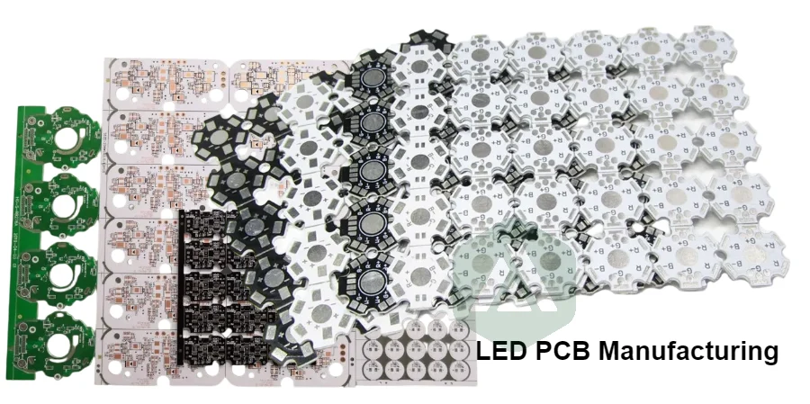
LED PCB selection is fundamentally a thermal design decision. The PCB is not only an electrical interconnection platform; in many lighting products it is a critical part of the heat path between the LED junction and the final heatsink or enclosure.
A poorly selected substrate can cause higher junction temperature, reduced brightness, color shift, accelerated lumen depreciation and premature product failure. A well-designed LED PCB combines the correct material system, copper structure, thermal interface and manufacturing process to maintain stable performance over the product lifetime.
At APTPCB, we manufacture LED PCBs using FR-4, high-Tg materials, HDI, flex, rigid-flex, metal core (MCPCB), ceramic and other advanced PCB technologies. Our LED PCB manufacturing approach focuses on matching thermal requirements with manufacturable stack-up solutions.
How do you choose the right LED PCB material?
The correct LED PCB material depends on four primary engineering inputs:
- LED power and heat density
- Maximum allowable junction temperature
- Available cooling path to the enclosure or heatsink
- Reliability and lifetime requirements
The highest thermal conductivity material is not always the correct choice. A low-power indicator board may be over-engineered with ceramic, while a high-power lighting module may fail quickly when built on standard FR-4.
LED PCB material selection matrix
| Application requirement | Recommended PCB material | Typical thermal approach | Common applications |
|---|---|---|---|
| Low-power LED, limited heat generation | FR-4 | Copper area, thermal vias, external airflow | Indicators, small displays, control boards |
| Moderate-power LED lighting | Aluminum MCPCB | Conductive dielectric layer and metal base | Commercial lighting, strips, downlights |
| High thermal density applications | Copper MCPCB or advanced MCPCB | Maximum heat spreading through metal core | Automotive lighting, industrial lamps |
| Extreme temperature or CTE-sensitive designs | Ceramic PCB | Direct thermal path and semiconductor-compatible expansion | COB LEDs, medical, aerospace |
The selection process should begin with thermal requirements rather than starting from a preferred material.
Why does thermal management matter in LED PCB manufacturing?
LED lifetime is strongly influenced by junction temperature. As heat accumulates around the LED package, electrical efficiency decreases and optical performance changes.
The complete thermal path is:
LED junction → LED package → solder joint → copper pad → PCB dielectric/substrate → metal core or thermal vias → heatsink → ambient environment
Every layer adds thermal resistance. The PCB material and construction determine how effectively heat leaves the LED package.
For high-power LEDs, the PCB often becomes the limiting factor because the thermal path through the board can dominate the overall design.
Is FR-4 suitable for LED PCBs?
FR-4 remains the most common PCB material because it offers low cost, mechanical stability and excellent electrical performance. However, standard FR-4 has relatively low thermal conductivity, typically around 0.2–0.5 W/m·K depending on laminate construction.
FR-4 works well when:
- LED power is low
- LEDs are widely spaced
- Heat can escape through another mechanical structure
- Thermal vias provide an effective heat path
For improved thermal performance, engineers may use:
- Larger copper areas
- Heavier copper weights
- Thermal via arrays
- Thin FR-4 constructions
- External heatsinks
For high-power LED modules where the PCB itself must remove significant heat, FR-4 often becomes the thermal bottleneck.
Why is MCPCB widely used for high-power LED lighting?
Metal Core PCB (MCPCB), also called aluminum PCB or insulated metal substrate (IMS), is the most common thermal solution for LED lighting.
A typical MCPCB structure contains:
- Copper circuit layer
- Thermally conductive dielectric layer
- Aluminum or copper metal base
The heat path becomes shorter and more efficient because the metal core spreads heat toward the heatsink.
Aluminum MCPCB vs copper MCPCB
| Feature | Aluminum MCPCB | Copper MCPCB |
|---|---|---|
| Thermal performance | High | Very high |
| Cost | Moderate | Higher |
| Weight | Lower | Higher |
| Manufacturing availability | Excellent | More specialized |
| Typical applications | General lighting, industrial LEDs | Extreme power density designs |
For many LED products, aluminum MCPCB provides the best balance between thermal performance, cost and production scalability.
The dielectric layer is especially important because it electrically isolates the copper circuit from the metal core while controlling thermal resistance. A thinner dielectric with higher thermal conductivity can significantly improve heat transfer.
When should ceramic PCB be used for LED applications?
Ceramic PCB technology is selected when thermal performance, temperature stability or coefficient of thermal expansion (CTE) control becomes more important than cost.
Common ceramic materials include:
- Aluminum oxide (Al₂O₃)
- Aluminum nitride (AlN)
Ceramic substrates provide:
- Excellent thermal conductivity
- High-temperature resistance
- Good dimensional stability
- Strong compatibility with semiconductor devices
They are commonly used for:
- Chip-on-board LED assemblies
- Automotive headlamps
- High-brightness LEDs
- Medical and aerospace lighting systems
Ceramic PCBs usually involve higher material and processing costs, so they are typically reserved for applications where aluminum MCPCB cannot meet thermal or reliability targets.
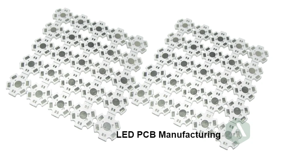
What LED PCB design factors affect thermal performance?
Material selection establishes the thermal foundation, but PCB design determines whether that capability is fully used.
Thermal vias and copper spreading
For FR-4 LED boards, thermal vias provide a vertical heat path between copper layers. Via diameter, copper plating thickness, spacing and connection to thermal planes all influence performance.
Copper thickness
Higher copper weight improves current handling and lateral heat spreading.
Common copper choices include:
- 1 oz copper for standard applications
- 2 oz copper for improved current and heat distribution
- Higher copper weights for specialized power designs
Thermal dielectric selection
For MCPCB designs, specify:
- Dielectric thermal conductivity
- Dielectric thickness
- Electrical isolation requirements
- Long-term reliability under temperature cycling
The dielectric is often the most important thermal bottleneck inside an MCPCB structure.
Surface finish and solder mask
LED applications may also require optical considerations.
Examples:
- White solder mask can improve light reflection in lighting modules.
- Surface finish must support reliable LED solder joints.
- Material compatibility must be maintained during assembly processes.
What are the common LED PCB thermal failure modes?
| Failure mode | Primary cause | Design impact |
|---|---|---|
| Reduced brightness over time | Excessive junction temperature | Faster lumen depreciation |
| LED color shift | Uneven thermal conditions | Optical inconsistency |
| Solder joint cracking | Thermal cycling stress | Intermittent failures |
| PCB delamination | Poor material compatibility or processing | Reduced reliability |
| Premature LED failure | Insufficient heat removal | Shortened product lifetime |
Thermal design should consider the complete operating environment, including ambient temperature, enclosure design, airflow and duty cycle.
What should engineers ask an LED PCB manufacturer?
Selecting a PCB supplier requires more than confirming that MCPCB or ceramic capability exists.
LED PCB supplier checklist
| Evaluation area | Questions to confirm |
|---|---|
| Material capability | Can the supplier manufacture FR-4, MCPCB and ceramic structures required for the project? |
| Thermal design support | Does engineering review the heat path and stack-up before production? |
| Dielectric control | Are dielectric thickness and thermal conductivity specified and controlled? |
| Manufacturing quality | Are lamination, drilling, plating and inspection processes controlled? |
| Testing | Can thermal performance and electrical reliability be validated? |
| Production scalability | Can prototype designs transition into stable mass production? |
A reliable LED PCB partner should help convert thermal requirements into a manufacturable board structure.
How does APTPCB support LED PCB manufacturing?
LED PCB manufacturing requires coordination between electrical design, thermal engineering and production capability.
APTPCB supports LED applications through:
- Material selection guidance across FR-4, MCPCB, ceramic and advanced PCB platforms
- Thermal stack-up optimization
- DFM review before production
- Manufacturing support for complex PCB structures
- PCBA integration when required
Our experience with PCB fabrication processes allows LED designers to balance thermal performance, reliability and cost.
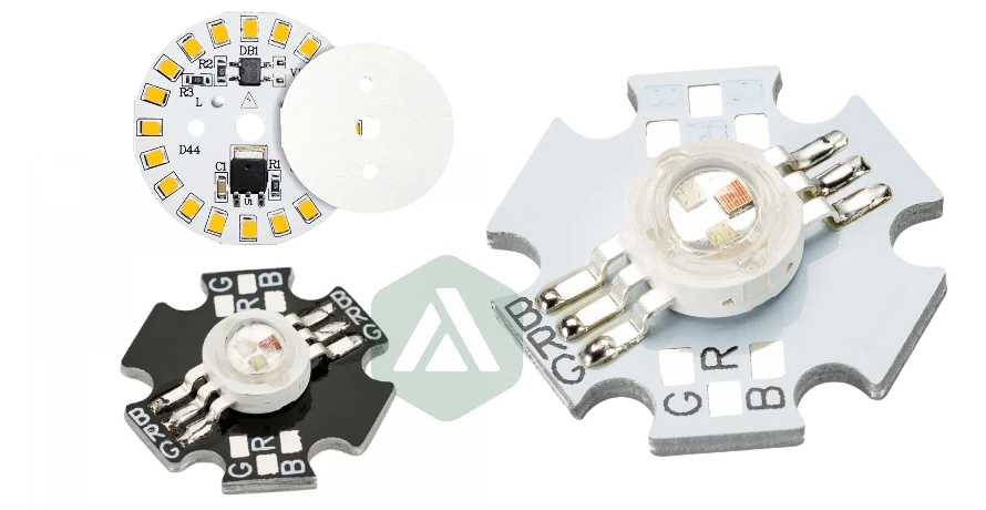
How can you optimize LED PCB performance before production?
The most reliable LED products are designed with thermal management from the beginning.
Before manufacturing, define:
- LED operating power
- Maximum junction temperature
- Heat sink or enclosure design
- Required lifetime
- PCB material and stack-up requirements
- Production volume expectations
APTPCB applies advanced manufacturing experience, including advanced PCB manufacturing techniques and multi-layer laminated structures expertise, to create LED PCB solutions optimized for real-world performance.
For demanding applications, detailed engineering review and PCB quality control help ensure that thermal performance remains consistent from prototype through mass production.