
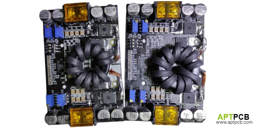
Teams evaluating an MPPT controller PCB are usually not asking whether the maximum power point tracking algorithm works. The production question is whether the board can move from converter concept to a repeatable assembly that keeps high-current paths, sensing accuracy, thermal behavior, interfaces, and factory verification under control.
If the project centers on energy conversion, charging, or storage hardware, start with power and energy PCB builds. If the board also manages equipment signals, cabinet interfaces, or supervisory control, include the review requirements used for industrial control PCB builds.
Quick Answer
Review an MPPT controller PCB as a manufacturing decision package, not only as a schematic and layout exercise. The release package should prove that the switching stage, sensing boundary, HVDC isolation, thermal route, assembly process, and functional test method agree before the first production build.
What Should an MPPT Controller PCB Review Decide Before RFQ?
A useful review answers five release questions:
- Are the power-conversion loops separated from analog measurement and control regions?
- Are panel, battery, load, and communication interfaces physically understandable for assembly and service?
- Does the thermal path match the real enclosure, mounting method, and operating environment?
- Can the assembly process handle large power components, connectors, and mixed technology parts?
- Can production test verify the finished board without redesigning access points?
The highest-risk MPPT board problems usually appear when these decisions are left between teams. A schematic may define electrical intent, while manufacturing needs connector orientation, probe locations, thermal constraints, isolation boundaries, and assembly assumptions.
Which MPPT PCB Review Areas Need the Most Attention?
| Review area | Decision to make | Production impact if unresolved |
|---|---|---|
| Power-stage partitioning | Define switching loops, current paths, and noisy regions | EMI problems, heating, unstable converter behavior |
| Sensing boundary | Protect voltage, current, and temperature measurement paths | Calibration drift, false protection events, debug delays |
| HVDC isolation | Define creepage, clearance, slots, and coating boundaries | Safety failures and field reliability issues |
| Thermal path | Match copper, heatsink, enclosure, and airflow decisions | Component overstress and reduced lifetime |
| Assembly route | Confirm SMT, THT, selective solder, and mechanical processes | Yield loss and rework difficulty |
| Functional test | Define sources, loads, fixtures, and measurement access | Slow bring-up and inconsistent validation |
This matrix turns the review into a release decision rather than a collection of isolated layout comments.
How Should Power Stage and Control Areas Be Partitioned?
An MPPT controller combines a switching converter, current and voltage measurement, protection circuits, firmware control hardware, and communication interfaces. The first PCB review task is deciding where high-energy switching activity ends and where sensitive measurement begins.
The switching region should remain compact. High-current paths should be short and direct, especially around switching devices, input capacitors, inductors, current sensing elements, and output capacitors.
Review these physical boundaries:
- The main switching loop is compact and clearly identified.
- Battery and panel current paths remain controlled before reaching connectors.
- Feedback traces do not cross switch-node copper.
- MCU, communication, and low-level analog circuits remain separated from noisy power areas.
- Protection circuits remain accessible for validation.
For MPPT systems connected directly to photovoltaic strings, isolation planning becomes a manufacturing boundary. A board connected to 150VDC, 600VDC, or higher PV input requires controlled creepage and clearance decisions, including isolation slots and conformal-coating keep-out areas where required.
The fabrication package should define these requirements clearly rather than relying on generic CAD spacing rules. HVDC routing, milling requirements, and coating boundaries are part of the safety design.
When a product combines a power board with a separate user interface, communications module, or supervisory controller, define that architecture early. A single PCB is not always the lowest-risk solution.
How Should Sensing Accuracy Be Reviewed on an MPPT Controller PCB?
MPPT performance depends on reliable voltage and current measurements. The PCB review must confirm that sensing circuits remain stable while operating next to high-current switching activity.
The sensing review should cover:
- Current shunt or sensor placement relative to high-current return paths.
- Voltage divider placement and routing away from switching nodes.
- Temperature-sensor placement near relevant thermal sources.
- Reference and ground strategy for measurement circuits.
- Calibration and debug access after assembly.
A sensing point that disappears under a connector, heatsink, shield, or tall magnetic component becomes a manufacturing problem even if the schematic is correct.
The completed assembly should still provide practical access for measuring:
- input voltage;
- battery output voltage;
- charge current;
- temperature feedback;
- fault and status signals.
How Do You Choose the Thermal Design Route for an MPPT PCB?
Thermal decisions should start with the actual installation environment. Copper thickness, thermal vias, heatsinks, and specialty materials only work when they connect to a realistic heat-removal path.
That is where high thermal PCB builds become useful. The correct choice depends on component location, enclosure design, mounting pressure, airflow, and assembly constraints.
Review:
- MOSFET, diode, shunt, and magnetic component locations.
- Copper spreading capability around heat-generating parts.
- Heat transfer path into chassis or heatsink structures.
- Clearance around connectors and service areas.
- Compatibility between thermal hardware and assembly operations.
A thermal solution that blocks inspection, prevents fixture contact, or complicates soldering can create production problems even if laboratory temperatures appear acceptable.
What Interface Checks Should Be Completed Before Layout Freeze?
MPPT boards usually connect to more than the PCB itself. They interface with photovoltaic inputs, batteries, loads, communication systems, sensors, and enclosure wiring.
The interface review should confirm:
- Panel-side and battery-side power connectors are clearly separated.
- Harness routing does not interfere with service access.
- Connector locations support assembly sequence.
- Probe access remains available after mechanical installation.
- Tall components do not block terminals or inspection areas.
The board should communicate its intended assembly flow through the layout. Connector zones, mounting points, and test areas should be understandable without relying on tribal knowledge.
What Manufacturability Checks Should Be Completed Before Ordering?
An MPPT controller PCB often combines fine-pitch control components with large inductors, power packages, terminals, and mechanical hardware. That combination requires an assembly-focused review before RFQ.
The supplier package should include:
| Item | Review purpose |
|---|---|
| Gerber or ODB++ files | Verify manufacturing interpretation |
| BOM with alternates | Confirm sourcing and substitution limits |
| Stack-up information | Confirm copper and isolation requirements |
| Thermal notes | Define heat-transfer assumptions |
| Connector and harness drawings | Prevent mechanical integration issues |
| Assembly method | Confirm SMT, THT, selective solder, and hardware steps |
| Test requirements | Align fixtures and verification methods |
The assembly process should account for heavy copper areas, large thermal masses, selective solder requirements, and rework accessibility.
What Failure Modes Should an MPPT PCB Review Catch?
| Failure mode | Root cause | Review checkpoint |
|---|---|---|
| Converter instability | Excessive switching-loop area or noisy feedback routing | Power-stage layout review |
| Measurement errors | Poor sensing placement or noisy reference paths | Analog boundary review |
| Overheating | Undefined heat path or blocked thermal transfer | Mechanical and thermal review |
| Assembly delays | Hidden solder joints or inaccessible components | DFM inspection review |
| Slow production testing | Missing probe points or fixture assumptions | FCT planning review |
| HV reliability issues | Undefined creepage, clearance, or coating limits | Safety boundary review |
How Should Assembly and Functional Test Be Planned?
A production-ready MPPT controller PCB needs a clear path from assembly inspection to powered verification.
If the project needs board-level powered verification after assembly, route that planning to FCT test preparation.
The release package should define:
- expected startup sequence;
- protection and shutdown behavior;
- programmable source requirements;
- battery simulator or electronic load requirements;
- measurement points;
- fixture clearance around tall components;
- separation between bare-board checks, assembly inspection, and powered testing.
Functional testing should be designed together with the PCB rather than added after pilot production begins.
When Does This MPPT PCB Review Apply?
This review approach fits projects involving:
- MPPT controller board review;
- solar power conversion PCB development;
- battery charging controller assemblies;
- sensing and switching-stage layout review;
- industrial energy-control hardware.
Other topics require separate validation paths, including:
- solar energy-yield calculations;
- battery chemistry performance;
- EMC certification testing;
- communication protocol compliance;
- system-level field guarantees.
When Should You Request an MPPT PCB Manufacturing Review?
Prepare the RFQ package after the board review has confirmed:
- power-stage partitioning;
- sensing boundaries;
- thermal strategy;
- interface definitions;
- assembly process;
- functional-test expectations.
Then move to the quote request flow.
Next steps with APTPCB
If your solar MPPT controller, ESS inverter, or high-voltage charging platform requires a manufacturing review, provide the release package through [email protected] or upload files through the MPPT controller PCB review request.
The recommended package includes Gerber or ODB++, BOM, creepage and clearance requirements, thermal notes, and coating keep-out information for high-voltage regions and service interfaces.
APTPCB's power-conversion and DFM process team reviews manufacturing risks before prototype investment, helping identify layout, assembly, and verification issues before they become pilot-build delays.
Summary
An MPPT controller PCB review should connect electrical design, mechanical integration, manufacturing, and test planning into one release decision. The strongest boards are not only functional prototypes; they are assemblies with defined power boundaries, reliable sensing, controlled thermal paths, accessible interfaces, and a production-ready verification plan.
Public references
Texas Instruments, "AN-1149 Layout Guidelines for Switching Power Supplies"
Infineon, "PCB Design Guidelines For Switching Power Supplies"
Keysight, "Functional Test Systems for Electronics Manufacturing"
Author and review information
- Author: APTPCB power-conversion content team
- Technical review: PCB manufacturing, PCBA process, MPPT control-board review, and functional-test engineering team
- Last updated: 2025-03-07