MT ferrule connector interface reliability refers to the ability of a Mechanically Transferable (MT) multi-fiber ferrule to maintain consistent optical transmission and physical alignment under varying environmental and mechanical stresses. This reliability is governed by precise geometric parameters—such as fiber height, radius of curvature, and apex offset—that ensure all fibers (typically 12 to 72) maintain physical contact simultaneously.
Key Takeaways
- Definition: MT ferrule reliability depends on the collective physical contact of all fibers; a single fiber failure compromises the entire channel.
- Critical Metric: Insertion Loss (IL) must typically remain < 0.35 dB for low-loss applications to ensure signal integrity in high-speed networks.
- Geometry Threshold: The fiber height differential among all fibers in an array must generally be < 500 nm to prevent air gaps on shorter fibers.
- Misconception: A clean visual inspection does not guarantee reliability; interferometry is required to verify the 3D geometry of the ferrule face.
- Validation Tip: Always verify spring force (e.g., 10N for 12-fiber, 20N for 24-fiber) matches the connector housing specification to maintain mating pressure.
- Decision Rule: If the application uses Single-Mode (SM) fiber, you must use an Angled Physical Contact (APC) interface (8°) to meet Return Loss (RL) requirements of > 60 dB.
- Material Factor: Glass-filled Polyphenylene Sulfide (PPS) is the standard material for MT ferrules due to its dimensional stability during temperature cycling.
What It Really Means (Scope & Boundaries)
MT ferrule connector interface reliability is not merely about the connector housing (like MPO or MTP) but specifically concerns the precision-molded thermoplastic ferrule and the polished fiber array face. Unlike single-fiber connectors (LC, SC) where a ceramic ferrule holds one fiber, an MT ferrule holds 12, 16, 24, or even 72 fibers in a linear or multi-row array.
The core challenge is coplanarity. For a reliable connection, the mating force provided by the connector spring must deform the ferrule material slightly to bring all fiber tips into physical contact. If the "fiber height" (protrusion) varies too much, or if the ferrule face is too convex or concave, some fibers will float (air gap), causing high Insertion Loss (IL) and poor Return Loss (RL).
Scope of Reliability:
- Geometric Stability: The ferrule material (usually PPS) must not warp under heat (reflow or operating temp).
- Guide Pin Alignment: The stainless steel guide pins must align the two ferrules within roughly 1 µm tolerance to minimize core offset.
- End-face Quality: The polished surface must be free of scratches, pits, and contamination within the core zones (Zone A) and cladding zones (Zone B).
Boundaries: This guide focuses on the interface—the mating surface and alignment mechanism. It excludes the cable jacket flammability or the backend strain relief, except where they impact the interface geometry.
Metrics That Matter (How to Evaluate It)
To quantify MT ferrule connector interface reliability, engineers rely on two categories of metrics: Optical Performance (signal quality) and 3D Geometry (physical shape). Both must pass for a connector to be deemed reliable.
Optical Performance Metrics
These metrics determine if the signal passes through the interface correctly.
| Metric | Standard Range (Single-Mode) | Standard Range (Multi-Mode) | Why It Matters | Verification Method |
|---|---|---|---|---|
| Insertion Loss (IL) | < 0.75 dB (Std) / < 0.35 dB (Low Loss) | < 0.50 dB (Std) / < 0.35 dB (Low Loss) | High IL reduces link budget, limiting cable distance. | Power Meter & Light Source |
| Return Loss (RL) | > 60 dB (APC) | > 20 dB (PC) | Low RL causes signal reflection, increasing bit error rates (BER). | Optical Time Domain Reflectometer (OTDR) |
| Mating Durability | 500 cycles (change < 0.2 dB) | 500 cycles (change < 0.2 dB) | Ensures longevity in patch panels and test equipment. | Automated Mating Test |
| Operating Temp | -40°C to +75°C | -40°C to +75°C | Verifies material stability in data center or outdoor environments. | Environmental Chamber |
| Spring Force | 9.8N ± 1N (12-fiber) | 9.8N ± 1N (12-fiber) | Insufficient force fails to close air gaps; excessive force damages fibers. | Force Gauge |
3D Geometry (Interferometry) Metrics
These metrics ensure the physical contact is possible. If these fail, optical performance will likely fail or degrade over time.
| Metric | Acceptance Criteria (IEC 61755-3-31) | Impact on Reliability | Common Failure Mode |
|---|---|---|---|
| Radius of Curvature (X-axis) | > 2000 mm (effectively flat) | Ensures the ferrule face is flat enough for all fibers to touch. | Over-polishing creates a rounded face, disconnecting outer fibers. |
| Radius of Curvature (Y-axis) | 5 mm to 30 mm | Allows the ferrule to rock slightly to align angles. | Flat Y-axis prevents proper angular mating. |
| Fiber Height (Protrusion) | 1000 nm to 3500 nm | Ensures fibers protrude enough to contact the mating fiber. | Fibers polished too short (undercut) create air gaps. |
| Fiber Height Differential | < 500 nm (Max - Min) | Ensures coplanarity across the array. | One high fiber prevents neighbors from touching. |
| Adjacent Fiber Height Diff | < 300 nm | Prevents local gaps between neighboring channels. | Uneven polishing pressure. |
| Apex Offset | < 50 µm | Centers the highest point of the polish near the fiber array. | Angle polishing fixture misalignment. |
| Core Dip | < 50 nm (SM) | Prevents air gaps specifically at the light-carrying core. | Soft polishing films eroding the fiber core faster than cladding. |
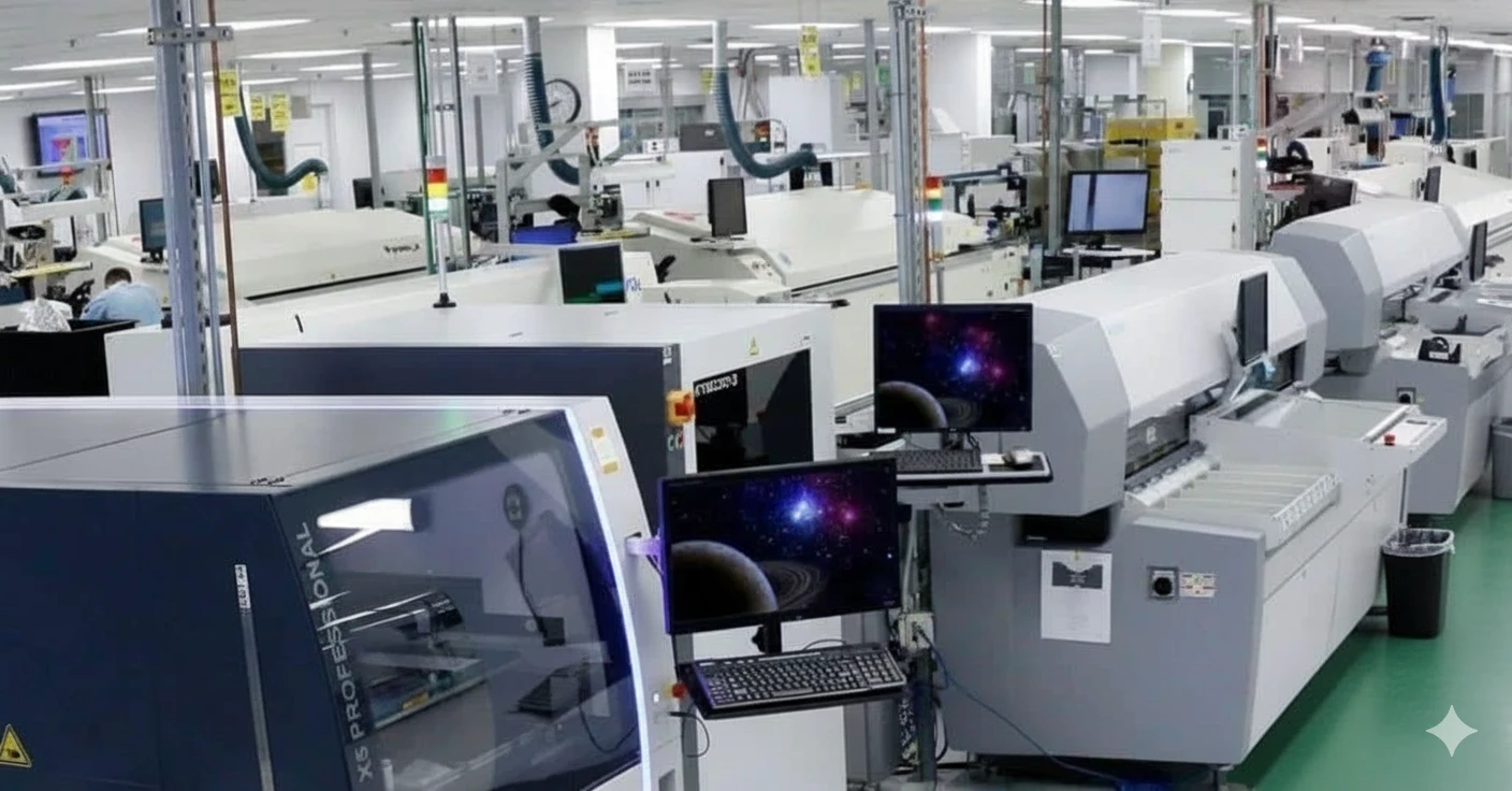
Figure 1: A reliability lab setup for verifying optical connector geometry and environmental stress testing.
How to Choose (Selection Guidance by Scenario)
Selecting the right MT ferrule configuration is a trade-off between cost, density, and performance requirements. Use these decision rules to navigate the options.
- If you are designing for 40G/100G Ethernet (SR4), choose a 12-fiber Multi-Mode (OM3/OM4) ferrule. Only the outer 8 fibers are typically used, but the 12-fiber format is the industry standard.
- If you require Single-Mode (SM) transmission, choose an APC (Angled Physical Contact) ferrule with an 8° angle. This is non-negotiable to achieve RL > 60 dB.
- If you are connecting Multi-Mode (MM) transceivers, choose a PC (Physical Contact) ferrule (0° flat polish). MM systems are less sensitive to reflections, and flat polishing is more cost-effective.
- If your link budget is tight (< 2.0 dB total), choose Low Loss (LL) MT ferrules. These have tighter bore tolerances (e.g., 125.5 µm vs. 126.0 µm) to reduce concentricity errors.
- If you need high density in a confined space (e.g., Communication Equipment PCB), choose a 16-fiber or 32-fiber MT ferrule (often used for 400G/800G applications). Note that 16-fiber ferrules use offset guide pins to prevent mating with 12-fiber systems.
- If the environment involves high vibration (e.g., Aerospace Defense PCB), choose a connector housing with enhanced spring force (20N) and a locking mechanism to prevent ferrule separation.
- If you are designing a backplane interconnect, choose blind-mate MT ferrules with floating mechanisms to absorb mechanical tolerances.
- If you are performing Cable Assembly, choose pinned (male) connectors for the equipment side (transceiver) and unpinned (female) connectors for the patch cord side to protect the delicate pins from damage.
- If cost is the primary driver for short links (< 10m), choose Standard Loss ferrules, but verify that the IL penalty does not exceed the transceiver's receiver sensitivity.
- If you are using Rigid-Flex PCB designs with board-mounted optical engines, choose low-profile MT ferrules (like PRIZM® LightTurn®) that mate directly to the board optics.
Implementation Checkpoints (Design to Manufacturing)
Ensuring MT ferrule connector interface reliability requires a strict process from incoming material checks to final testing.
Phase 1: Preparation & Polishing
- Incoming Inspection: Verify ferrule bore diameter and guide pin hole tolerance.
- Acceptance: Bore diameter 125 µm +1/-0 µm for SM Low Loss.
- Epoxy Application: Inject thermal-cure epoxy into the ferrule. Avoid air bubbles which cause fiber breaks during thermal expansion.
- Acceptance: 100% fill visible in the window; no voids > 10% of volume.
- Fiber Insertion: Insert stripped/cleaned fibers. Ensure fiber protrusion is uniform before curing.
- Acceptance: All fibers protrude > 200 µm before polishing.
- Curing: Follow a stepped temperature profile (e.g., 80°C -> 100°C -> 120°C) to minimize stress.
- Acceptance: Epoxy hardness > 85 Shore D.
Phase 2: Polishing & Geometry
- Polishing Sequence: Use a high-precision polishing machine with specific films (Silicon Carbide -> Diamond -> Silicon Dioxide).
- Acceptance: No scratches visible at 400x magnification.
- Interferometry Scan: Measure 3D geometry using a white-light interferometer.
- Acceptance: Radius X > 2000 mm; Fiber Height 1000-3500 nm; Differential < 500 nm.
- Cleaning: Use automated cleaners to remove polishing residue.
- Acceptance: Pass IEC 61300-3-35 (no loose debris in Zone A).
Phase 3: Assembly & Testing
- Housing Assembly: Install spring, pin keeper, and housing body.
- Acceptance: Spring force measured at 10N ± 1N (for standard 12-fiber).
- Optical Testing: Measure IL and RL at 1310nm/1550nm (SM) or 850nm/1300nm (MM).
- Acceptance: IL < 0.35 dB; RL > 60 dB (APC).
- End-Face Documentation: Capture a final digital image of the ferrule face for traceability.
- Acceptance: Image stored in Quality System database linked to serial number.
Common Mistakes (and the Correct Approach)
Reliability issues often stem from process deviations rather than component failure.
| Mistake | Impact on Reliability | Correct Approach | How to Verify |
|---|---|---|---|
| Mixing Guide Pin Gender | Mating two female connectors results in zero alignment; mating two males damages pins/fibers. | Strictly follow the "Transceiver = Male (Pinned), Patch Cord = Female (Unpinned)" rule. | Visual inspection of guide pins before mating. |
| Using Dry Wipes Only | Dry wiping moves static-charged dust around rather than removing it, scratching the PPS face. | Use a "Wet-to-Dry" cleaning method or specialized click-cleaners designed for MT ferrules. | Digital microscope inspection (IEC 61300-3-35). |
| Ignoring Spring Force | Weak springs cannot overcome the fiber protrusion force, leading to air gaps and high IL. | Verify spring force matches the fiber count (12F vs 24F require different forces). | Spring force gauge measurement during assembly. |
| Mating APC with PC | Creates a massive air gap and damages the fiber cores due to point contact. | Use color coding (Green = APC, Blue/Beige/Aqua = PC) and keying to prevent mismating. | Visual check of housing color and ferrule angle. |
| Over-Polishing (Undercut) | Fibers recede too far into the ferrule, making physical contact impossible. | Control polishing time and pressure; monitor "Fiber Height" metric closely. | Interferometer scan (negative fiber height is a fail). |
| Touching Ferrule End-face | Oils from skin degrade signal and can burn onto the fiber core if high power is used. | Always use dust caps; never touch the end-face. | Microscope inspection for oil smudges. |
| Assuming "Low Loss" is Automatic | Buying "Low Loss" components but using standard polishing processes yields standard results. | Use precision polishing fixtures and tighter process controls for Low Loss products. | IL testing (must be < 0.35 dB). |
| Neglecting Guide Pin Holes | Debris in pin holes prevents full mating, creating a gap across the entire array. | Clean guide pin holes with specialized micro-swabs or compressed air. | Check for "gap" between connector housings when mated. |
FAQ (Cost, Lead Time, Materials, Testing, Acceptance Criteria)
1. How much more expensive are MT ferrule assemblies compared to LC/SC? MT ferrule assemblies typically cost 5x to 10x more per connector than single-fiber LC connectors due to the complexity of the ferrule molding, the precision of the guide pins, and the difficulty of polishing 12+ fibers simultaneously. However, the cost per fiber is often lower in high-density applications.
2. What is the typical lead time for custom MT ferrule cable assemblies? Standard lead times range from 2 to 4 weeks. High-fiber-count assemblies (e.g., 72-fiber) or custom breakout configurations may extend this to 6 weeks depending on the availability of specific Cable Assembly components and the capacity of the polishing line.
3. Can I repair a damaged MT ferrule interface? Generally, no. If the fiber cores are scratched or chipped, re-polishing is rarely successful because it alters the critical length and geometry of the ferrule. The standard procedure is to cut off the connector and terminate a new one, which shortens the cable assembly.
4. Why is Interferometry mandatory for MT ferrules but optional for some LC connectors? In single-fiber (LC) connectors, the ferrule floats freely, allowing the spring to easily establish contact. In MT ferrules, the entire array is rigid. If the geometry (flatness/angle) is slightly off, the spring cannot compensate, leading to gaps on specific fibers. Interferometry is the only way to guarantee the 3D shape is correct.
5. What is the difference between MPO and MTP? MPO (Multi-fiber Push On) is the generic interface standard defined by IEC-61754-7. MTP® is a specific brand of MPO connector manufactured by US Conec. MTP connectors have design enhancements, such as a floating ferrule and removable housing, which often provide better mechanical reliability and Testing Quality.
6. How do I validate the reliability of an MT interface in a vibrating environment? You must perform a vibration test according to IEC 61300-2-1. This involves monitoring the optical signal for discontinuities (> 1.0 dB drop) while subjecting the mated pair to sinusoidal vibration (10
Glossary (key terms)
| Term | Meaning | Why it matters in practice |
|---|---|---|
| DFM | Design for Manufacturability: layout rules that reduce defects. | Prevents rework, delays, and hidden cost. |
| AOI | Automated Optical Inspection used to find solder/assembly defects. | Improves coverage and catches early escapes. |
| ICT | In-Circuit Test that probes nets to verify opens/shorts/values. | Fast structural test for volume builds. |
| FCT | Functional Circuit Test that powers the board and checks behavior. | Validates real function under load. |
| Flying Probe | Fixtureless electrical test using moving probes on pads. | Good for prototypes and low/medium volume. |
| Netlist | Connectivity definition used to compare design vs manufactured PCB. | Catches opens/shorts before assembly. |
| Stackup | Layer build with cores/prepreg, copper weights, and thickness. | Drives impedance, warpage, and reliability. |
| Impedance | Controlled trace behavior for high-speed/RF signals (e.g., 50Ω). | Avoids reflections and signal integrity failures. |
| ENIG | Electroless Nickel Immersion Gold surface finish. | Balances solderability and flatness; watch nickel thickness. |
| OSP | Organic Solderability Preservative surface finish. | Low cost; sensitive to handling and multiple reflows. |
Conclusion
MT ferrule connector interface reliability is easiest to get right when you define the specifications and verification plan early, then confirm them through DFM and test coverage.
Use the rules, checkpoints, and troubleshooting patterns above to reduce iteration loops and protect yield as volumes increase.
If you’re unsure about a constraint, validate it with a small pilot build before locking the production release.