An outdoor LED driver is the power engine responsible for regulating voltage and current to LED modules in harsh environmental conditions. Unlike indoor counterparts, these units must withstand temperature extremes (-40°C to +60°C), moisture ingress (IP65+), and high-energy electrical surges common in street and architectural lighting. Designing or selecting the right driver requires strict adherence to thermal limits, surge protection ratings, and component derating factors to ensure the standard 50,000-hour service life.
Quick Answer (30 Seconds)
- Surge Protection Rule: Outdoor drivers must withstand at least 4kV (Line-Line) and 6kV (Line-Earth) surges to survive lightning strikes and grid transients.
- Thermal Pitfall: Failing to derate electrolytic capacitors; for every 10°C drop in operating temperature, capacitor life typically doubles.
- Verification: Perform a 100% Burn-In Test at full load for 4–8 hours at 40°C–50°C ambient to screen for infant mortality.
- Boundary Case: Cold start capability is critical; ensure the driver can ignite LEDs at -40°C within 500ms.
- DFM Requirement: Ensure the LED Driver PCB layout maintains >6.4mm creepage between primary and secondary sides for safety compliance (IEC 61347).
Highlights
- Topology Selection: When to use Buck, Boost, or Flyback based on input/output voltage ratios.
- Environmental Protection: Differences between conformal coating and full potting for IP67.
- Component Derating: Specific limits for capacitors and MOSFETs in outdoor applications.
- Troubleshooting: Diagnosing flickering, dead units, and EMI failures.
- Testing Standards: Essential pass/fail criteria for safety and performance.
Contents
- Definition and Scope (What It Is, What It Isn’t)
- Rules and Specifications (Key Parameters and Limits)
- Implementation Steps (Process Checkpoints)
- Troubleshooting (Failure Modes and Fixes)
- How to Choose (Design Decisions and Trade-Offs)
- FAQ (Cost, Lead Time, Materials, Testing, Acceptance Criteria)
- Glossary (Key Terms)
- Request a Quote (DFM Review + Pricing)
Definition and Scope (What It Is, What It Isn’t)
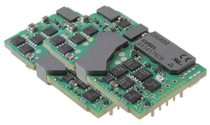
An outdoor LED driver is a self-contained power supply that converts AC line voltage (or DC sources) into a regulated DC current or voltage suitable for driving LEDs, specifically engineered to resist environmental stress.
Applies when:
- Street Lighting: High-power (50W–300W) drivers requiring high surge immunity and strict efficiency (>92%).
- Architectural/Landscape: Systems exposed to rain, irrigation, or soil acidity requiring IP67 or IP68 ratings.
- High-Bay/Industrial: Unconditioned spaces with extreme temperature fluctuations.
- Solar Lighting: DC-DC converters (Buck/Boost) managing battery charging and LED driving.
- Signage: Constant voltage drivers powering long LED strip runs outdoors.
Doesn’t apply when:
- Indoor Residential: Low-cost bulbs (A19, GU10) where thermal and surge requirements are minimal (1kV surge is often sufficient).
- Consumer Electronics: USB-powered LED gadgets.
- Conditioned Environments: Office lighting where IP20 is acceptable and temperature is stable (20°C–25°C).
Rules and Specifications (Key Parameters and Limits)
The following table outlines the non-negotiable parameters for a robust outdoor LED driver. Deviating from these ranges significantly increases the risk of field failure.
| Rule / Parameter | Recommended Value/Range | Why it matters | How to verify | If ignored |
|---|---|---|---|---|
| Input Voltage Range | 90–305 VAC (Universal) | Accommodates global grids and voltage swells (e.g., 277V systems peaking at 300V). | Variable AC source test from 85V to 310V. | Driver failure during grid fluctuations or inability to sell globally. |
| Surge Protection | L-N: 4kV / L-G: 6kV | Outdoor lines are antennas for lightning and switching transients. | IEC 61000-4-5 Surge Generator test. | Catastrophic failure (blown MOV/fuse) during storms. |
| Ingress Protection | IP65 (Damp) / IP67 (Wet) | Prevents moisture corrosion on the LED Driver PCB. | Dust chamber and immersion tank testing (30 mins @ 1m). | Short circuits, corrosion, and safety hazards within months. |
| Power Factor (PF) | > 0.95 (@ >50% load) | Utilities penalize low PF; reduces grid losses. | Power Analyzer measurement at 100%, 75%, 50% load. | Utility fines or disqualification from energy rebates (DLC). |
| THD (Current) | < 10% (@ full load) | High harmonics cause neutral heating and interfere with other grid equipment. | Power Analyzer harmonic analysis (up to 40th harmonic). | Grid pollution and potential flicker issues. |
| Efficiency | > 90–94% | Reduces internal heat; critical for sealed (potted) enclosures. | (Output Power / Input Power) × 100. | Overheating, reduced lifetime, and higher energy costs. |
| Case Temperature (Tc) | Max 80°C–85°C | Electrolytic capacitor life halves for every 10°C rise. | Thermocouple on the hottest spot (usually transformer or FET) during thermal steady state. | Premature failure (e.g., 50k hours drops to 10k hours). |
| Output Ripple Current | < 5% (Flicker-free) | Prevents stroboscopic effects and ensures camera compatibility. | Oscilloscope measurement of AC component on DC output. | Visible flicker, headaches, and security camera banding. |
| Leakage Current | < 0.75 mA | Safety requirement to prevent shock during installation/maintenance. | Hi-Pot tester (Leakage test mode). | Safety certification failure (UL/CE) and shock hazard. |
| Start-up Time | < 500 ms | Ensures lights turn on instantly; critical for safety lighting. | Oscilloscope trigger on AC input vs. Light Output. | Perceived "lag" or failure in emergency lighting specs. |
Implementation Steps (Process Checkpoints)
Designing and manufacturing an outdoor LED driver involves specific process steps to ensure reliability.

1. Topology Selection
Choose the power stage based on power level and isolation requirements.
- < 75W: Single-stage Flyback (High PF, Isolated, Simple).
- 75W – 150W: Two-stage (PFC + Flyback/LLC).
- > 150W: Two-stage (Boost PFC + LLC Resonant Converter) for high efficiency (>93%).
- DC Input (Solar): Buck LED Driver (if Vin > Vout) or Boost LED Driver (if Vin < Vout).
2. Component Selection & Derating
Outdoor drivers require automotive-grade or industrial-grade components.
- Capacitors: Use 105°C rated electrolytic capacitors with long life (e.g., 10,000 hours @ 105°C). Avoid 85°C generic caps.
- MOSFETs: Derate voltage by 20% (e.g., use 600V FET for 400V bus) and current by 30-50%.
- Magnetics: Use high-temperature bobbins and wire (Class F 155°C or Class H 180°C).
3. PCB Design and Layout
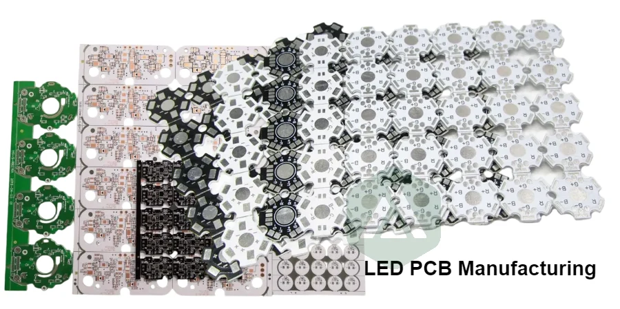
The LED Driver PCB is the foundation.
- Creepage/Clearance: Maintain >6.4mm (Reinforced Insulation) between Primary (AC) and Secondary (DC) for 230VAC inputs.
- Trace Width: Size high-current traces for **<10°C temperature rise**. Use Heavy Copper PCB (2oz or 3oz) for high-power drivers (>150W).
- Thermal Vias: Place dense via arrays under MOSFETs and Diodes to transfer heat to the case or heatsink.
4. Thermal Management
Heat is the enemy of longevity.
- MCPCB: For the LED module itself, use a Metal Core PCB (Aluminum or Copper) to dissipate heat.
- Driver Heatsinking: Attach power components to the aluminum enclosure using thermal pads or potting compound.
- Potting: Fill the enclosure with thermally conductive silicone or epoxy (typically 0.5–1.0 W/mK) to distribute heat and exclude moisture.
5. Protection Circuitry
Integrate robust protection features.
- Input: Fuse (Slow blow) + MOV (Metal Oxide Varistor) + GDT (Gas Discharge Tube) for surge.
- Output: OVP (Over Voltage Protection) prevents damage if the LED string opens.
- Short Circuit: Hiccup mode (auto-recovery) is preferred over latch-off.
- OTP: Over-Temperature Protection should throttle current (derate) rather than shut down completely, if possible.
6. Assembly and Potting
- Soldering: Ensure high-quality solder joints (IPC-A-610 Class 2 or 3).
- Cleaning: Thoroughly clean flux residues before potting to prevent chemical reactions or leakage paths.
- Vacuum Potting: Use vacuum chambers to remove air bubbles from the potting compound, ensuring no voids exist for moisture accumulation or thermal hotspots.
Troubleshooting (Failure Modes and Fixes)
Failures in outdoor drivers often manifest after installation. Here is how to diagnose them.
1. The "Dead" Driver (No Output)
- Symptom: Light does not turn on; no output voltage.
- Likely Cause: Input surge destroyed the MOV and Fuse.
- Check: Measure continuity across the AC input fuse. Inspect MOV for burning/cracking.
- Fix: Replace the unit. For design, upgrade MOV rating (e.g., from 14mm to 20mm diameter) or add a series surge protector.
2. Flickering or Strobing
- Symptom: Light flashes periodically (e.g., 1Hz) or shimmers.
- Likely Cause:
- Hiccup Mode: Output short circuit or overload triggers protection, resets, and triggers again.
- Incompatible Dimmer: TRIAC dimmer used with a non-dimmable or 0-10V driver.
- Electrolytic Cap Failure: Dried-out output caps cause excessive ripple.
- Check: Disconnect LED load and measure Vout. If it pulses, check for shorts. Check dimmer compatibility.
- Fix: Remove short on LED line. Replace driver with correct dimming type.
3. Early Failure (Weeks/months)
- Symptom: Driver works initially but fails after the first rain or cold snap.
- Likely Cause: Moisture ingress due to poor potting or seal failure.
- Check: Open the case. Look for corrosion, water droplets, or "mealing" on the PCB.
- Fix: Improve IP rating. Ensure cable glands are tightened to torque specs. Use Conformal Coating under the potting for double protection.
4. Emi/radio Interference
- Symptom: Security cameras show lines/noise, or radio reception drops when lights are on.
- Likely Cause: Failed or insufficient EMI filter (Common Mode Choke / X-Caps).
- Check: Spectrum analyzer test. Check grounding connection.
- Fix: Ensure the driver case is properly bonded to Earth Ground. Add ferrite beads to input/output cables.
5. Overheating (Thermal Shutdown)
- Symptom: Light turns off after 1-2 hours, then turns back on after cooling.
- Likely Cause: Ambient temperature exceeds rating, or heatsink is blocked.
- Check: Measure Tc (Case Temp). Ensure the driver is not mounted in a sealed, insulated box without airflow.
- Fix: Relocate driver to a cooler spot or ensure contact with a metal pole/fixture for conduction cooling.
How to Choose (Design Decisions and Trade-Offs)
Selecting the right driver architecture depends on the specific application constraints.
Constant Current (Cc) vs. Constant Voltage (Cv)
- If you are driving a direct series string of high-power LEDs (e.g., Streetlight module), choose Constant Current (CC). This ensures consistent brightness and prevents thermal runaway.
- If you are driving multiple parallel LED strips with onboard resistors (e.g., Signage, Cove lighting), choose Constant Voltage (CV) (usually 12V, 24V, or 48V).
Class I vs. Class Ii
- If the installation has a reliable Earth Ground connection, choose Class I. The metal case is grounded for safety and EMI shielding.
- If the installation has no ground (plastic housing, 2-wire input), choose Class II. This requires double insulation and stricter safety distances on the PCB.
Dimming Protocols
- If retrofitting existing lines, choose 0-10V (Analog) or Phase Cut (Residential).
- If smart city control is required, choose DALI-2 or D4i. These digital protocols allow two-way communication (reporting power usage, faults).
Ac vs. Dc Input
- If grid-connected, choose AC LED Driver (Universal 90-305V).
- If battery/solar powered, choose DC LED Driver.
- Use Buck if Battery Voltage > LED Voltage.
- Use Boost if Battery Voltage < LED Voltage.
- Use Buck-Boost if Battery Voltage varies above and below LED Voltage.
FAQ (Cost, Lead Time, Materials, Testing, Acceptance Criteria)
Q: What is the difference between "Dry," "Damp," and "Wet" location drivers?
- Dry: Indoor only (IP20). Open frame or vented case.
- Damp: Protected from humidity but not direct rain (IP64/IP65). Often conformal coated.
- Wet: Direct rain/snow exposure (IP67/IP68). Fully potted or hermetically sealed.
Q: Why is potting necessary for outdoor drivers?
- Thermal: Transfers heat from components to the case.
- Mechanical: Protects against vibration (wind load on poles).
- Electrical: Increases dielectric strength, allowing tighter component spacing.
- Chemical: Blocks moisture, salt mist, and dust.
Q: How do I test the lifetime of an LED driver?
- ALT (Accelerated Life Test): Run the driver at elevated temperatures (e.g., 85°C ambient) and apply the Arrhenius equation to predict life at normal temps (e.g., 40°C).
- Electrolytic Cap Calculation: Measure the ripple current and temperature of the output capacitors and compare against the manufacturer's lifetime curves.
Q: What is the typical warranty for an outdoor LED driver?
- Standard commercial grade: 5 years.
- Premium/Industrial grade: 7 to 10 years.
- Warranty is usually valid only if the Case Temperature (Tc) remains below the specified limit (e.g., 75°C).
Q: Can I use a 100W driver for a 50W load?
- Yes, but: Check the efficiency curve. Drivers are most efficient near 90-100% load. At 50% load, efficiency and Power Factor often drop significantly.
- Ensure the driver's minimum output voltage range includes the voltage of your 50W LED string.
Q: What is "Flicker-Free" and how is it measured?
- It refers to low Percent Flicker (<5%) and low Flicker Index (<0.02).
- It is achieved by using two-stage topologies or large output capacitance to smooth the 100Hz/120Hz ripple from the AC line.
Q: What files are needed to manufacture an LED Driver PCB?
- Gerber Files: Copper layers, solder mask, drill files.
- BOM (Bill of Materials): Specific part numbers, especially for critical magnetic and power components.
- Assembly Drawings: Polarity markings for diodes/caps.
- Potting Specs: Material type and fill level.
Q: How does "Smart" lighting affect the driver?
- Smart drivers need an Auxiliary Power Supply (e.g., 12V/24V aux output) to power sensors or wireless nodes (Zigbee/LoRa) without needing a separate power brick.
Glossary (Key Terms)
| Term | Meaning | Why it matters in practice |
|---|---|---|
| MOV | Metal Oxide Varistor | The primary component that absorbs voltage surges. If undersized, the driver fails during storms. |
| PFC | Power Factor Correction | Circuitry that aligns input current with voltage. Mandatory for loads >25W in most regions. |
| THD | Total Harmonic Distortion | Measure of how much the driver distorts the AC grid waveform. Lower is better. |
| IP Rating | Ingress Protection | IP65 = Water jets; IP67 = Temporary immersion. Critical for outdoor survival. |
| NTC | Negative Temperature Coefficient | A thermistor used for inrush current limiting or temperature sensing (thermal foldback). |
| PWM | Pulse Width Modulation | A method of dimming LEDs by turning them on/off rapidly. Can cause flicker if frequency is low (<1kHz). |
| CCR | Constant Current Reduction | Analog dimming method (reducing amplitude). Flicker-free but may cause color shift at low levels. |
| SELV | Safety Extra Low Voltage | Output voltage <60V DC. Safe to touch; simplifies fixture insulation requirements. |
| MTBF | Mean Time Between Failures | Statistical reliability prediction. Note: MTBF is not the same as service life. |
| DALI | Digital Addressable Lighting Interface | Standard protocol for individual control of drivers in a networked system. |
Request a Quote (DFM Review + Pricing)
When requesting a quote for LED Driver PCB manufacturing or full turnkey assembly, precision in documentation prevents delays. At APTPCB, we specialize in high-reliability power electronics.
Checklist for RFQ:
- Gerber Files: RS-274X format preferred.
- Centroid File: Pick-and-place coordinates.
- BOM: Include manufacturer part numbers for all power components (FETs, Magnetics, Caps). Specify "No Substitutes" on critical safety parts.
- PCB Specs: Copper weight (e.g., 2oz, 3oz), Tg (e.g., Tg170), and surface finish (ENIG recommended for flatness).
- Testing Requirements: Specify if Functional Circuit Test (FCT), Burn-In, or Hi-Pot testing is required.
- Potting/Coating: Specify material type (Silicone/Epoxy) and thickness/volume if turnkey box build is needed.
Conclusion
The reliability of an outdoor lighting system is almost entirely dependent on the quality of the Outdoor LED Driver. By adhering to strict rules regarding surge protection (4kV/6kV), thermal management (Tc < 85°C), and ingress protection (IP67), designers can ensure their products withstand the elements for a decade or more. Whether you are designing a custom Boost LED Driver for solar applications or a high-power AC street light driver, validating the design against these practical limits is the key to reducing field failures and maintenance costs.