Most PCB discussions start with layer count and routing rules. In practice, the thing that limits you much earlier is simpler: what is this board actually made of?
For basic products, a generic FR-4 stack-up is fine. But as soon as you run into any of the following:
- multi-gigabit links with a tight signal-integrity budget
- power-dense layouts where temperature and safety margins matter
- long-life operation in hot, humid, or vibrating environments
- customers who care about how the PCB looks — deep black cores, pure white solder mask, or even transparent boards
“any FR-4” stops being a safe answer.
At that point you don’t just need a material name; you need a material strategy: how to trade off electrical, thermal, mechanical, visual, and cost constraints; which layers really require high-frequency, high-thermal, or high-Tg materials and where enhanced FR-4 is enough; and a factory that actually knows how to turn those choices into stable, high-yield PCBs.
1. Why PCB Material Selection Matters More Than Ever
Modern electronics place extreme demands on the PCB:
- Signal Integrity: As edge rates increase, loss tangent (Df), dielectric constant (Dk), copper roughness, and glass weave all affect timing, impedance, and crosstalk.
- Thermal Performance: Power electronics and LEDs generate heat that must be efficiently spread and dissipated.
- Reliability: Temperature cycles, vibration, and humidity stress the resin system, copper adhesion, and via structures.
- Form Factor: Thinner cores, flex constructions, and dense multilayers drive mechanical and processing challenges.
- Aesthetics and Color: Visible boards in consumer, automotive, and lighting products must also look perfect — consistent color, clean surfaces, sharp silkscreen, no cosmetic defects.
The result: PCB material choice directly influences performance, reliability, manufacturability, appearance, and cost. Treating it as a late-stage “procurement detail” often leads to redesigns, unexpected cost increases, or customer complaints about both function and cosmetics.
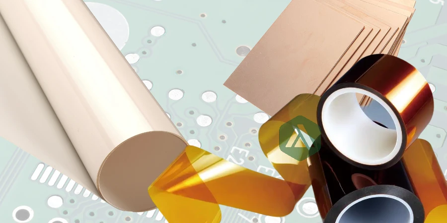
2. Key Categories of PCB Materials and When to Use Them
Different applications demand different material families. Below are several of the most important categories — including performance-driven and appearance-driven use cases.
2.1 High-Frequency and RF Materials
For RF front-ends, radar, 5G, and high-speed digital links, low loss and stable Dk are critical. Standard FR-4 quickly becomes the limiting factor.
Dedicated RF laminates, such as Rogers high-frequency materials or other low-loss systems, provide:
- low and stable Dk over frequency and temperature,
- low loss tangent (Df) for reduced insertion loss,
- better phase stability for phased-array and timing-critical designs.
Typical applications include base stations, satellite communication, radar, and high-speed backplanes.
2.2 High-Thermal and Power Electronics Materials
In power conversion, LED lighting, motor drives, and automotive systems, heat is often the biggest reliability threat.
Options such as high-thermal PCBs help by:
- providing efficient conduction from hot components into heatsinks or chassis,
- reducing hotspot temperatures,
- improving lifetime of semiconductors, LEDs, and passives.
Using the right high-thermal base material often reduces the need for oversized heatsinks or forced cooling, making designs more compact and efficient.
2.3 Flex and Flex–Rigid Materials
Where space is tight or movement is required — wearables, medical probes, folding devices, gimbals, or aerospace harness replacement — flexible materials come into play.
A well-designed flex PCB stack-up can:
- eliminate connectors and wiring harnesses,
- reduce assembly complexity,
- improve reliability in dynamic bending zones,
- enable thinner, lighter mechanical designs.
Material selection must account for bend radius, copper type (rolled vs. ED), coverlay, and stiffener strategy to ensure both flexibility and durability.
2.4 Ceramic and Hybrid Substrates
For very high temperature, high power density, or extreme reliability requirements, ceramic PCBs offer:
- excellent thermal conductivity,
- high dielectric strength and stability,
- low CTE mismatch with certain semiconductor materials.
They are commonly used in power modules, RF power amplifiers, aerospace, defense, and high-end industrial applications where failure is not an option.
2.5 High-Tg and Enhanced FR-4 Materials
Many designs still use an FR-4 family material, but not all FR-4 is the same. High-Tg PCBs improve:
- glass transition temperature (Tg),
- thermal stability under lead-free reflow,
- resistance to repeated thermal cycling.
High-Tg and enhanced FR-4 variants are often used in automotive, industrial control, and other harsh environments where standard FR-4 margins are too thin.
2.6 Aesthetic, Color-Critical, and Optical Materials
Some customers care just as much about how the PCB looks as how it performs electrically. Typical examples include:
- premium consumer devices where the PCB is partly visible,
- automotive interiors and HMIs where color and gloss must match the design language,
- lighting and architectural products using exposed or backlit boards.
In these cases, PCB material and stack-up decisions also need to consider:
Color and Core Appearance:
Black core constructions — supported through engineered multilayer structures such as those used in black-core / special laminated PCBs — can provide a deep, uniform black look that hides internal circuitry and prevents light leakage.Surface Color and Finish:
High-opacity whites, deep matte blacks, or custom colors demand compatible solder mask systems and material combinations to avoid color shift, patchiness, or transparency issues.Transparent and Semi-Transparent PCBs:
For some display, sensor, and lighting applications, customers request transparent PCBs that make copper traces visually “float” or disappear. These typically rely on special substrates and processing approaches that fall under special PCB manufacturing — with strict control of cleanliness, scratch resistance, and cosmetic inspection criteria.
For these projects, visual quality (color consistency, surface flatness, scratch/dust control, silkscreen sharpness) becomes a formal part of the PCB specification, not an afterthought.
3. Balancing Electrical, Thermal, Mechanical, Aesthetic, and Cost Constraints
Choosing the “right” material is always a multi-dimensional trade-off:
- Electrical: Dk, Df, weave style, thickness tolerance, and copper roughness influence impedance and loss.
- Thermal: Conductivity, specific heat, and Tg determine how the board behaves under power and reflow.
- Mechanical: CTE, modulus, and flex behavior affect warpage, via reliability, and mechanical integration.
- Aesthetic/Optical: Core color, mask color, opacity, gloss, and transparency affect how the board looks in the final product, especially under strong lighting or behind glass.
- Processing: Lamination temperature, drillability, and copper-to-resin systems affect yield and cost.
- Cost and Availability: Premium materials must still be commercially viable over the product lifetime.
A high-speed, visually exposed board, for example, might combine a low-loss RF core for signals, a high-Tg FR-4 for mechanical robustness, and a black core or specific solder mask system to achieve the required color and contrast. A power-dense LED module may pair a high-thermal base with carefully chosen white solder mask and printing to meet both performance and visual expectations.
4. From Material List to Manufacturable Stack-Up
Even after you choose candidate materials, turning them into a manufacturable PCB requires careful engineering.
4.1 Matching Materials to Roles in the Stack
Different layers may serve different roles:
- RF or high-speed signal layers built on low-loss or RF materials
- Power and ground planes on robust FR-4 or high-Tg cores
- Thermal spreaders or high-thermal layers near hot components
- Flex layers in hinge or dynamic regions
- Dark cores or specific mask systems where aesthetic and light-blocking are critical
A well-designed stack-up often blends multiple materials while keeping processing and cost under control.
4.2 Availability, Risk, and Long-Term Support
Some advanced laminates have longer lead times or limited regional availability. Reviewing the supplier landscape and documentation helps ensure:
- you are not locking the product into a single fragile supply,
- there is a realistic path for volume production,
- alternative materials exist if demand or regulations change.
Early collaboration between design, procurement, and your PCB manufacturer is essential to avoid surprises later.
5. How a Manufacturing Partner Adds Value to PCB Material Selection
The best results come when material choice, stack-up, and process are defined together. A capable factory does more than just “accept your stack-up” — it helps you refine it.
5.1 Material Consulting and Trade-Off Analysis
Experienced engineers can:
- recommend suitable low-loss, high-thermal, high-Tg, or ceramic options,
- explain trade-offs between cost, loss, and processing difficulty,
- suggest where premium materials are truly needed — and where enhanced FR-4 is enough,
- advise on color, opacity, and surface systems for demanding visual requirements.
5.2 Process Know-How for Special Materials and Visual Specs
Each material family, and each visual requirement, has its own process “personality”:
- lamination cycles and pressures,
- optimal drill parameters and desmear conditions,
- copper preparation and bonding chemistry,
- reflow and thermal profiles,
- mask thickness, curing, and inspection for color-critical or transparent builds.
A shop experienced with low-loss laminates, high-thermal structures, flex materials, ceramics, black-core constructions, and transparent / special PCBs can build stable processes around these variables and deliver consistent yield and appearance.
6. Summary: Treat PCB Material and Appearance as Design Parameters
The performance, reliability, and perceived quality of your product are tightly coupled to your PCB material selection — including both what happens electrically inside the board and how the board looks from the outside.
Whether your design calls for:
- low-loss RF materials similar to those used in Rogers-based solutions,
- high-thermal substrates as in high-thermal PCB designs,
- compact and dynamic constructions built on flexible PCB materials,
- high-reliability builds with high-Tg materials,
- extreme-environment modules on ceramic PCBs, or
- visually striking black-core or transparent boards enabled by multi-layer laminated structures and special PCB manufacturing,
the right combination of materials, stack-up, appearance strategy, and process will determine how far your product can go.
By working with a partner who understands both the science of materials and the reality of manufacturing and aesthetics, you can turn bold ideas — electrically and visually — into reliable, manufacturable hardware without letting the PCB substrate become the bottleneck to your next innovation.