Definition, scope, and who this guide is for
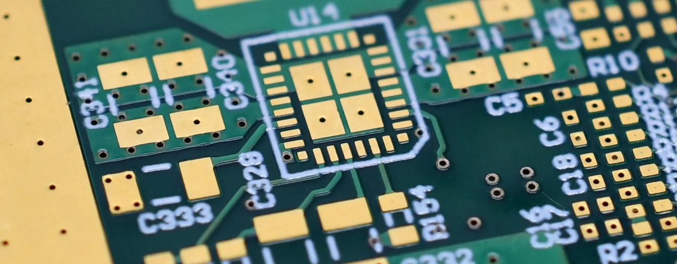
A PCIe Gen6 backplane PCB prototype represents the physical validation of high-speed interconnect architecture designed to support data transfer rates of 64 GT/s using PAM4 signaling. Unlike standard printed circuit boards, these backplanes act as the central nervous system for servers, storage arrays, and networking gear, often requiring high layer counts (20+), ultra-low loss materials, and precise backdrilling to eliminate signal stubs. The transition from simulation to a physical prototype is the most critical phase in hardware development, as it confirms whether the signal integrity (SI) models hold true in a real-world manufacturing environment.
This guide is written for hardware architects, signal integrity engineers, and procurement leads who are tasked with sourcing these complex boards. It moves beyond basic definitions to provide a structured approach to specification, risk mitigation, and supplier validation. The goal is to help you navigate the tight tolerances required for PAM4 signaling and ensure your first prototype run yields functional boards that can be reliably tested.
At APTPCB (APTPCB PCB Factory), we understand that a prototype is not just a sample; it is a proof of engineering competence. This playbook consolidates best practices to help you minimize iteration cycles and avoid common pitfalls associated with high-speed material handling and multilayer lamination.
When to use PCIe Gen6 backplane PCB prototype (and when a standard approach is better)
Understanding the scope of your project is the first step; knowing when to commit to the cost and complexity of a Gen6 build is the second.
Deploy a PCIe Gen6 backplane PCB prototype when:
- Throughput is Non-Negotiable: Your system architecture demands 64 GT/s per lane to support AI/ML clusters, high-frequency trading platforms, or next-gen data center switches.
- PAM4 Signaling is Required: You are moving away from NRZ (Non-Return-to-Zero) encoding. PAM4 introduces four voltage levels, significantly reducing the noise margin and requiring stricter impedance control than Gen5.
- Future-Proofing Modular Designs: You are designing a chassis intended to last multiple hardware generations, requiring the backplane to support current Gen5 cards while being ready for Gen6 upgrades.
- Complex Topology: The design involves long trace lengths (up to 20 inches) where insertion loss becomes the primary bottleneck, necessitating advanced materials and connector footprints.
Stick to Standard Gen4/Gen5 Backplanes when:
- Cost is the Primary Driver: The materials required for Gen6 (e.g., Megtron 7/8, Tachyon) are significantly more expensive than standard FR4 or mid-loss laminates.
- Legacy Compatibility: The system only interfaces with older peripherals that do not require PAM4 signal clarity.
- Short Trace Lengths: If the signal path is very short, the benefits of ultra-low loss materials may be negligible compared to the cost.
PCIe Gen6 backplane PCB prototype specifications (materials, stackup, tolerances)
Once you have determined that a Gen6 solution is necessary, you must define rigid specifications to ensure the manufacturer can meet the signal integrity requirements.
- Base Material (Laminate): Must use Ultra-Low Loss materials. Common choices include Panasonic Megtron 7 (or 8), Isola Tachyon 100G, or Rogers RO4000 series for hybrid stacks.
- Target Df (Dissipation Factor): < 0.002 @ 10 GHz.
- Target Dk (Dielectric Constant): Stable across frequency (3.0 – 3.4).
- Copper Foil Roughness: HVLP (Hyper Very Low Profile) or VLP2 copper is mandatory.
- Reason: At 32 GHz (Nyquist for 64 GT/s), skin effect is dominant. Rough copper increases conductor loss significantly.
- Layer Count & Thickness: Typically 20 to 40 layers.
- Board Thickness: Often ranges from 3.0mm to 6.0mm (0.120" to 0.240").
- Aspect Ratio: High aspect ratios (up to 20:1 or 25:1) for plated through holes (PTH).
- Impedance Control:
- Differential Impedance: 85Ω or 100Ω (depending on architecture).
- Tolerance: Stricter than standard; aim for ±5% or ±7% rather than the standard ±10%.
- Backdrilling (Controlled Depth Drilling): Mandatory for all high-speed via stubs.
- Stub Length: Must be < 6-8 mils (0.15mm - 0.20mm) to prevent resonance issues.
- Backdrill Diameter: Typically drill diameter + 8 mils clearance.
- Surface Finish: Immersion Silver or ENIG (Electroless Nickel Immersion Gold).
- Preference: Immersion Silver is often preferred for lower insertion loss, though ENIG is common for shelf life.
- Via Technology:
- Use of blind and buried vias is common but adds cost.
- Press-fit connector holes must meet strict finished hole size tolerances (typically ±0.05mm).
- Glass Weave Style: Spread glass (e.g., 1067, 1078, 1086) is required to mitigate Fiber Weave Effect (FWE), which causes skew between differential pairs.
- Registration Tolerance: Layer-to-layer registration must be tight (±3-5 mils) to ensure backdrills do not sever internal traces.
- Cleanliness: Ionic contamination levels must be strictly controlled to prevent electrochemical migration (ECM) in high-voltage data center environments.
PCIe Gen6 backplane PCB prototype manufacturing risks (root causes and prevention)
Defining specs is only half the battle; understanding where the manufacturing process typically breaks down allows you to preempt failures.
Signal Skew due to Fiber Weave Effect
- Root Cause: Differential pair traces running parallel to the glass weave bundles; one leg runs over glass, the other over resin.
- Detection: Massive jitter seen in eye diagrams during testing.
- Prevention: Specify "spread glass" styles or rotate the design on the panel (10-degree rotation) to average out the dielectric constant.
Backdrill Depth Errors (Stub Remnants or Cut Traces)
- Root Cause: Variation in board thickness or drill machine Z-axis accuracy.
- Detection: TDR (Time Domain Reflectometry) shows unexpected impedance dips; open circuits if drilled too deep.
- Prevention: Use "controlled depth" drilling with electrical sensing; ensure the manufacturer adds specific "stop layers" or copper pads for the drill to sense.
Plated Through Hole (PTH) Barrel Cracks
- Root Cause: High aspect ratio (thick board, small hole) combined with thermal expansion mismatch during reflow.
- Detection: Intermittent failures during thermal cycling or IST testing.
- Prevention: Ensure copper plating thickness in holes is sufficient (avg 25µm, min 20µm); use high-Tg materials with low Z-axis CTE.
Impedance Deviations due to Etch Factor
- Root Cause: Trapezoidal shape of traces after etching (top width < bottom width) affects impedance.
- Detection: Cross-section analysis or coupon testing fails impedance specs.
- Prevention: Manufacturer must perform accurate etch compensation on the artwork; DFM review must confirm trace width adjustments.
Pad Cratering under Press-Fit Connectors
- Root Cause: Mechanical stress during connector insertion damages the resin beneath the copper pad.
- Detection: Dye and pry testing or micro-sectioning.
- Prevention: Use "teardrops" on pads; ensure resin is fully cured; follow connector manufacturer's press-fit specifications strictly.
Inner Layer Misregistration
- Root Cause: Material movement (scaling) during the lamination of 30+ layers.
- Detection: X-ray inspection shows misalignment; shorts or opens in extreme cases.
- Prevention: Use pin-lamination techniques; manufacturer must apply scaling factors based on material behavior data.
Conductive Anodic Filament (CAF) Growth
- Root Cause: Electrochemical migration along the glass fibers between vias.
- Detection: High-voltage insulation resistance testing.
- Prevention: Use CAF-resistant materials; maintain sufficient wall-to-wall clearance between vias (0.8mm - 1.0mm pitch requires careful planning).
Resin Starvation
- Root Cause: Heavy copper layers (power planes) prevent resin from flowing into clearance areas during lamination.
- Detection: Visual voids or delamination in cross-sections.
- Prevention: Balance copper distribution; use high-flow prepregs where necessary.
PCIe Gen6 backplane PCB prototype validation and acceptance (tests and pass criteria)

To ensure your PCIe Gen6 backplane PCB prototype is ready for assembly and system integration, a rigorous validation plan is required.
- Impedance Testing (TDR):
- Objective: Verify differential impedance matches 85Ω/100Ω targets.
- Method: Time Domain Reflectometry on test coupons and actual board traces.
- Acceptance: All tested lines within ±5% (or agreed ±7%) tolerance.
- Insertion Loss Measurement (VNA):
- Objective: Confirm signal loss per inch meets the loss budget for Gen6.
- Method: Vector Network Analyzer measurement up to 32 GHz.
- Acceptance: Loss curve matches simulation (e.g., < 1.0 dB/inch @ 16 GHz) within 10%.
- Cross-Section Analysis (Micro-sectioning):
- Objective: Verify stackup construction, plating thickness, and drill alignment.
- Method: Destructive physical analysis of a coupon or scrap board.
- Acceptance: Copper thickness > 20µm in holes; no cracks; dielectric thickness matches stackup.
- Backdrill Verification:
- Objective: Ensure stubs are removed without damaging internal connections.
- Method: X-ray inspection or micro-sectioning of backdrilled vias.
- Acceptance: Stub length < 8 mils; minimum insulation distance to internal layers maintained.
- Interconnect Stress Test (IST) or HATS:
- Objective: Validate via reliability under thermal stress.
- Method: Thermal cycling (e.g., 260°C reflow simulation) followed by resistance monitoring.
- Acceptance: Resistance change < 10% after 6 simulated reflow cycles.
- Press-Fit Hole Tolerance Check:
- Objective: Ensure connector pins will fit securely without damaging the board.
- Method: Pin gauge or coordinate measuring machine (CMM).
- Acceptance: Finished hole size within ±0.05mm of spec.
- Solderability Test:
- Objective: Ensure surface finish accepts solder properly.
- Method: IPC-J-STD-003 wetting balance test.
- Acceptance: > 95% coverage; no de-wetting.
- Bow and Twist Measurement:
- Objective: Ensure board flatness for assembly and chassis installation.
- Method: Measurement on a surface plate.
- Acceptance: < 0.75% (or < 0.5% for strict requirements) across the diagonal.
PCIe Gen6 backplane PCB prototype supplier qualification checklist (RFQ, audit, traceability)
When selecting a partner for a PCIe Gen6 backplane PCB prototype, general capabilities are insufficient. Use this checklist to vet suppliers specifically for high-speed, high-layer-count work.
Group 1: RFQ Inputs (What you must provide)
- Complete Gerber files (RS-274X or X2) or ODB++.
- Detailed Stackup Drawing (specifying material types by name, not just "FR4").
- Drill Chart distinguishing between PTH, NPTH, and Backdrills.
- Impedance Control Table (Layer, Trace Width, Spacing, Reference Plane).
- Netlist (IPC-356) for electrical test verification.
- Fabrication Drawing with notes on Class 3 requirements and tolerances.
- Press-fit connector specifications (hole size requirements).
- Panelization requirements (if assembly is automated).
Group 2: Capability Proof (What they must demonstrate)
- Experience with Megtron 7/8 or Tachyon materials (ask for past project examples).
- Capability to handle Aspect Ratios > 20:1.
- Automated Backdrilling equipment with depth-sensing technology.
- Lamination presses capable of high-pressure/vacuum for >30 layers.
- In-house VNA/TDR testing up to 40 GHz.
- Laser drilling capability for microvias (if HDI is used).
Group 3: Quality System & Traceability
- IPC-6012 Class 3 qualification.
- UL certification for the specific material stackup proposed.
- Automated Optical Inspection (AOI) for inner layers (100% inspection).
- X-ray capability for registration verification.
- Material certificates of conformance (CoC) from the laminate supplier.
- Calibration records for impedance testing equipment.
Group 4: Change Control & Delivery
- Formal Engineering Change Order (ECO) process.
- DFM report provided before manufacturing begins.
- EQ (Engineering Query) process for resolving data ambiguities.
- Secure data handling (IP protection).
- Clear lead time schedule including material procurement time.
- Packaging standards (vacuum sealed with desiccant and humidity indicator).
How to choose PCIe Gen6 backplane PCB prototype (trade-offs and decision rules)
Every design decision involves a trade-off. Here is how to navigate the conflicting constraints of a PCIe Gen6 backplane PCB prototype.
- Material Cost vs. Signal Loss:
- Rule: If your trace length exceeds 10 inches, choose Megtron 7 or Tachyon despite the cost.
- Trade-off: If traces are < 5 inches, you might get away with Megtron 6 or mid-loss materials to save 30% on laminate costs, but you risk failing SI margins.
- Layer Count vs. Aspect Ratio:
- Rule: If you need more routing layers, you must increase board thickness.
- Trade-off: If thickness exceeds 4mm, ensure your via diameter is large enough to keep the aspect ratio under 20:1. If you keep vias small (0.2mm) on a thick board (5mm), plating reliability will fail.
- Backdrilling vs. Blind Vias:
- Rule: Use backdrilling for standard connector pins.
- Trade-off: Use blind vias only if density is extreme. Blind vias significantly increase lamination cycles and cost, whereas backdrilling is a post-lamination mechanical process that is cheaper but requires larger keep-out zones.
- Surface Finish: ENIG vs. Immersion Silver:
- Rule: If insertion loss is the absolute priority, choose Immersion Silver.
- Trade-off: If the boards will be stored for months before assembly, choose ENIG for better oxidation resistance, accepting a slight hit on signal loss due to nickel's magnetic properties.
- Prototype Speed vs. DFM Quality:
- Rule: Never skip the DFM review to save 2 days.
- Trade-off: A "quick turn" that skips detailed engineering review often results in a scrap board due to overlooked impedance or registration issues. Always allocate 2-3 days for EQ (Engineering Questions).
PCIe Gen6 backplane PCB prototype FAQ (cost, lead time, Design for Manufacturability (DFM) files, materials, testing)
Q: What is the primary cost driver for a PCIe Gen6 backplane PCB prototype? A: The base laminate material (e.g., Megtron 7) and the layer count are the biggest factors. High-speed materials can cost 3-5x more than standard FR4, and high layer counts increase lamination labor and yield risk.
Q: What is the typical lead time for a PCIe Gen6 backplane PCB prototype? A: Standard lead time is 15-20 working days. However, if the specific high-speed material is not in stock, procurement can add 2-4 weeks; always check material stock status during the quote phase.
Q: Which DFM files are critical for PCIe Gen6 backplane PCB prototype manufacturing? A: Beyond Gerbers, the IPC-356 netlist and a detailed stackup file (with dielectric constants specified) are critical. Without the netlist, the manufacturer cannot verify that the finished board matches your electrical logic.
Q: Can I use standard FR4 for a PCIe Gen6 backplane PCB prototype to save money? A: No. Standard FR4 has a loss tangent (Df) that is too high (0.020 vs 0.002), which will destroy the signal integrity of 64 GT/s PAM4 signals, rendering the prototype useless for validation.
Q: How does backdrilling affect the cost of a PCIe Gen6 backplane PCB prototype? A: Backdrilling adds roughly 10-15% to the board cost depending on the number of holes. It requires a separate CNC setup and specialized depth-control programming.
Q: What are the acceptance criteria for impedance testing on these prototypes? A: Most designs require ±10% tolerance, but for Gen6, we recommend requesting ±5% or ±7%. TDR coupons should be included on the panel rails to allow testing without damaging the actual board.
Q: Do I need to specify "spread glass" for my PCIe Gen6 backplane PCB prototype? A: Yes. Standard weave glass creates periodic gaps that cause skew in differential pairs. Specifying spread glass (like 1067 or 1078) ensures a uniform dielectric environment for the signals.
Q: What testing is performed to ensure the backplane won't fail in the field? A: Apart from electrical testing, Interconnect Stress Testing (IST) is recommended for prototypes to verify that the high-aspect-ratio vias can withstand thermal cycling without barrel cracking.
Resources for PCIe Gen6 backplane PCB prototype (related pages and tools)
To further assist in your design and procurement process, utilize these specific resources from APTPCB:
- Backplane PCB Manufacturing: Deep dive into the specific capabilities required for large-format, high-layer-count backplanes.
- High-Speed PCB Capabilities: Learn about the manufacturing techniques used to preserve signal integrity for PCIe, Ethernet, and DDR applications.
- Panasonic Megtron Materials: Detailed specifications on the Megtron family, the industry standard for Gen6 applications.
- Impedance Calculator: A tool to help you estimate trace widths and spacing for your required 85Ω or 100Ω differential pairs.
- DFM Guidelines: Essential design rules to ensure your complex backplane is manufacturable at scale.
Request a quote for PCIe Gen6 backplane PCB prototype (Design for Manufacturability (DFM) review + pricing)
Ready to move from design to hardware? Submit your data for a comprehensive DFM review and accurate pricing. For a PCIe Gen6 backplane PCB prototype, please include your Gerber files, stackup details, drill chart, and any specific impedance requirements.
Request a Quote and DFM Review – Our engineering team will review your stackup and material selection to ensure Gen6 compliance before production begins.
Conclusion (next steps)
Successfully delivering a PCIe Gen6 backplane PCB prototype requires more than just sending files to a fab house; it demands a partnership focused on material science, precision drilling, and rigorous validation. By adhering to strict specifications for low-loss materials and backdrilling, and by proactively managing manufacturing risks like registration and skew, you ensure your prototype provides accurate data for system validation. APTPCB is equipped to handle these complexities, ensuring your transition from design to physical hardware is seamless and reliable.