
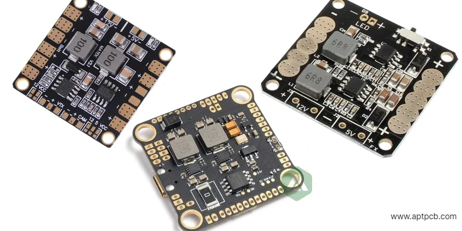
A power distribution board PCB distributes electrical power from one or more sources to multiple protected loads while managing current paths, switching, monitoring, and fault isolation. A reliable design depends on the complete electrical path: copper, vias, connectors, protection devices, terminals, joints, and thermal environment.
A “100 A power board” is not defined only by copper weight. The actual capability depends on branch loading, allowable temperature rise, connector ratings, contact resistance, airflow, enclosure conditions, and fault behavior.
What information is needed before requesting a power distribution PCB quote?
A supplier can only evaluate manufacturing feasibility when the electrical and environmental requirements are defined. The RFQ package should describe:
- Input voltage range and transient conditions.
- Continuous, peak, startup, and fault current for each branch.
- Simultaneous-load assumptions and duty cycles.
- Connector and harness specifications.
- Protection requirements and fault recovery behavior.
- Operating temperature, airflow, enclosure, and installation conditions.
- Required monitoring, communication, and calibration accuracy.
- Inspection, testing, and production traceability requirements.
Power distribution PCB requirement decision matrix
| Requirement | Design decision | RFQ evidence |
|---|---|---|
| Branch current | Size copper, vias, terminals, and protection devices from actual current profile | Branch current table with continuous, peak, and surge values |
| Voltage level | Define insulation system, component ratings, and spacing requirements | Voltage range, transient category, and applicable standard |
| Thermal limit | Determine copper area, heat spreading, cooling method, and sensor placement | Temperature-rise requirement and test conditions |
| Fault capability | Coordinate protection with source and downstream loads | Fuse, breaker, current-limit, or isolation behavior |
| Mechanical interface | Select connectors, mounting, busbars, and harness interfaces | Approved part numbers and mechanical drawings |
| Manufacturing volume | Determine process controls and inspection level | Prototype, pilot, and production forecast |
How should current capacity be specified for a power distribution PCB?
Current capacity should be defined by branch and by operating condition. A board carrying multiple loads may have a high-current input path while individual outputs operate at lower currents.
The branch power budget should include:
| Input | Why it matters | RFQ evidence |
|---|---|---|
| Source voltage and tolerance | Determines insulation, protection, and component ratings | Power architecture and transient requirements |
| Continuous/peak current by branch | Determines copper, vias, terminals, and switches | Load table with duty cycle |
| Available fault current | Determines interruption capability and conductor stress | Source impedance or fault-current limit |
| Ambient, airflow, enclosure | Determines allowable temperature rise | Worst-case thermal condition |
| Harness and connector | Adds resistance and heating | Exact mating parts and cable details |
| Redundancy or hot-swap behavior | Changes isolation and inrush requirements | Fault sequence description |
How do copper weight, vias, and busbars affect high-current PCB performance?
High-current power distribution boards are designed as complete current networks. Copper thickness alone does not determine performance.
IPC-2152 calculations — or a first-pass IPC-2221 estimate in the PCB trace width calculator — provide a starting point for conductor sizing, but final capability depends on:
- copper geometry;
- internal and external layer distribution;
- via quantity and current sharing;
- laminate construction;
- heat spreading;
- airflow;
- connection resistance.
| Construction | Useful when | Main design consideration |
|---|---|---|
| Wide heavy-copper regions | Moderate-to-high current planar routing | Copper geometry and local heating |
| Parallel layers with via arrays | Compact multilayer current distribution | Via current sharing and barrel heating |
| Embedded or attached busbar | Very high current or low voltage-drop requirements | Joint resistance and mechanical stress |
| Press-fit or bolted terminals | Serviceable high-current connections | Torque, contact resistance, and plating |
Voltage-sense connections should measure the actual load path. A convenient measurement point that bypasses a high-resistance connection can produce misleading readings.
How should power protection be coordinated on a distribution PCB?
Protection devices must be selected as part of the complete electrical system. A fuse, breaker, current limiter, or electronic protection circuit must match:
- source fault capability;
- conductor capability;
- connector limits;
- load characteristics;
- interruption requirements.
Each branch should define:
- reverse-polarity behavior;
- short-circuit response;
- overload response;
- inrush limiting;
- overvoltage protection;
- thermal shutdown behavior;
- reset or recovery sequence;
- safe state after control power loss.
Protection decisions also affect PCB layout. High-energy switching paths should be separated from sensitive measurement and communication circuits to reduce noise injection and measurement errors.
What creepage and clearance requirements apply to power distribution PCB design?
PCB insulation spacing depends on the complete application, not voltage alone. Requirements are influenced by:
- working voltage;
- transient category;
- pollution degree;
- insulation type;
- material group;
- coating;
- altitude;
- equipment standard.
Define high-energy zones, low-voltage control areas, chassis connections, protective earth paths, signal returns, and cable shields deliberately.
Slots, barriers, and coatings can contribute to insulation performance only when their materials and manufacturing processes are controlled.
How should thermal performance be verified?
Thermal performance must be demonstrated under realistic operating conditions. A temperature measurement without boundary conditions does not provide reusable qualification evidence.
Thermal validation should define:
- load current;
- simultaneous branch operation;
- ambient temperature;
- airflow;
- enclosure condition;
- measurement locations;
- stabilization time.
Sensors should represent the actual thermal hotspots, including terminals, fuse holders, switching devices, shunts, and connector interfaces.
Which tests should be included in a power distribution PCB RFQ?
| Test | Purpose |
|---|---|
| Four-wire resistance measurement | Verifies copper, vias, contacts, and joints |
| Loaded voltage-drop test | Confirms delivered voltage under specified current |
| Temperature-rise test | Identifies hottest qualified components and interfaces |
| Inrush and switching capture | Measures startup stress, ringing, and transient behavior |
| Protection fault injection | Confirms isolation and recovery behavior |
| Dielectric/ground test | Verifies insulation and bonding requirements |
| Functional telemetry test | Confirms sensing, alarms, communication, and calibration |
The production test plan should identify fixtures, measurement points, acceptance limits, and recorded data.
What should be included in a power distribution PCB RFQ package?
A complete RFQ package should include:
- Input/output voltage ranges and transient requirements.
- Branch current, duty cycle, and fault-current table.
- Protection architecture and safe-state requirements.
- PCB stack-up, copper distribution, and busbar requirements.
- Connector manufacturer part numbers and mechanical drawings.
- Creepage and clearance requirements.
- Monitoring circuits, shunts, sensors, and calibration requirements.
- Thermal environment and temperature limits.
- Inspection, electrical testing, and qualification requirements.
- Traceability, revision control, first article requirements, and production forecast.
Power distribution PCB supplier checklist
Before selecting a manufacturing partner, confirm that the supplier can provide:
| Supplier capability | Evidence to request |
|---|---|
| Heavy copper manufacturing | Copper thickness capability and sample builds |
| High-current assembly | Terminal, connector, and busbar process experience |
| Thermal validation support | Temperature test method and reporting format |
| Electrical testing | Resistance, functional, dielectric, or custom fixtures |
| Production control | Revision management and traceability records |
| Quality documentation | Inspection reports and qualification records |
A supplier-ready package reduces quotation delays because manufacturing decisions are based on defined electrical, thermal, and production requirements.
Review heavy-copper PCB, power and energy PCB and testing and quality, then submit the controlled package through the PCB quotation page.
Standards and references
- IPC-2152 — Current-carrying capacity of printed-board conductors
- IPC-2221 — Generic printed board design
- IPC-6012 — Qualification and performance for rigid printed boards
- IEC 60664-1 — Insulation coordination for low-voltage systems
- IEC 61439 series — Low-voltage switchgear and controlgear assemblies
- UL 508A — Industrial control panels
Confirm the current edition and the product standard governing the complete equipment.
Power distribution PCB FAQ
How much current can a PCB carry?
There is no universal current value. Capability depends on conductor geometry, copper distribution, cooling, temperature limits, and every connection in the current path.
Is heavier copper always the best solution?
No. Heavy copper, parallel copper layers, busbars, and alternative connector architectures each solve different current and thermal challenges.
Should every output have its own fuse?
Protection depends on the system architecture, load behavior, and fault-containment goals. Each branch requires a documented protection decision.
How should voltage drop be verified?
Measure source and load interfaces under defined current, thermal steady state, ambient conditions, and airflow. Four-wire methods are useful for low-resistance paths.
What information delays a power distribution PCB quote?
Missing branch currents, fault-current data, connector specifications, protection behavior, thermal conditions, and test requirements usually create the most uncertainty.