Contents
- The Context: What Makes Quantum Control PCB Challenging
- The Core Technologies (What Actually Makes It Work)
- Ecosystem View: Related Boards / Interfaces / Manufacturing Steps
- Comparison: Common Options and What You Gain / Lose
- Reliability & Performance Pillars (Signal / Power / Thermal / Process Control)
- The Future: Where This Is Going (Materials, Integration, Ai/automation)
- Request a Quote / DFM Review for Quantum Control PCB (What to Send)
- Conclusion
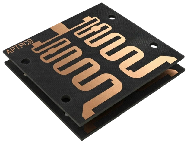
While the quantum processor (QPU) gets the headlines, the control board is the workhorse that makes operation possible. Good performance in this domain isn't just about connectivity; it is about extreme signal fidelity, minimal thermal noise, and the ability to suppress decoherence through precise flux control. For manufacturers like APTPCB (APTPCB PCB Factory), producing these boards requires a shift from standard fabrication to high-precision microwave engineering.
Highlights
- Signal Integrity is Paramount: Quantum states are fragile; control signals must be delivered with minimal attenuation and phase distortion.
- Material Selection Matters: Standard FR4 is often insufficient; low-loss materials like PTFE or ceramic-filled hydrocarbons are standard.
- Thermal Management: Many control boards operate near cryostats, requiring careful consideration of Coefficient of Thermal Expansion (CTE).
- Precision Manufacturing: Etching tolerances and layer registration must be tighter than IPC Class 3 standards to maintain impedance.
The Context: What Makes Quantum Control PCB Challenging
The fundamental challenge in quantum control is the fragility of the qubit. Whether the system uses superconducting transmons, trapped ions, or spin qubits, the control electronics must bridge the gap between room-temperature instrumentation and the quantum environment. This creates a unique set of pressures on the PCB design.
First, density is becoming a bottleneck. As researchers scale from dozens to hundreds of qubits, the number of coaxial lines and control traces explodes. A Quantum Control PCB must route these high-frequency signals out of the cryostat or through the control rack without crosstalk. If channel A leaks into channel B, the quantum gate fidelity drops, leading to calculation errors.
Second, reliability takes on a new meaning. In many setups, changing a faulty board involves warming up a dilution refrigerator, which can take days or weeks. The board must work correctly the first time and maintain its performance over thousands of thermal cycles. This mirrors the reliability demands seen in aerospace and defense PCBs, where maintenance is costly or impossible.
Finally, lead time is often compressed. The quantum field moves fast. Research teams iterate on pulse sequences and control logic frequently, requiring hardware that can keep up with rapid prototyping cycles without sacrificing the precision of mass production.
The Core Technologies (What Actually Makes It Work)
To handle microwave pulses in the 4–8 GHz range (common for superconducting qubits) or RF signals for ion traps, the PCB relies on several core technologies.
- Low-Loss Dielectrics: The substrate is the foundation. Standard epoxy-glass laminates absorb too much signal energy at microwave frequencies. We often utilize Rogers or Taconic materials which offer a low Dissipation Factor (Df) and a stable Dielectric Constant (Dk). This ensures that the control pulse arrives at the qubit with the exact shape and timing intended.
- Controlled Impedance & Stack-up: Impedance mismatches cause signal reflections. In a quantum system, a reflection is not just power loss; it is noise that can dephase a qubit. The PCB stack-up is designed with extreme care, often mixing high-frequency cores with standard prepregs to balance performance and cost.
- Surface Finish & Skin Effect: At microwave frequencies, current travels along the outer skin of the copper trace. A rough copper profile or a resistive surface finish can degrade the signal. Immersion Silver or ENIG (Electroless Nickel Immersion Gold) are preferred over HASL because they provide a flat, conductive surface that minimizes insertion loss.
- Embedded Components & Shielding: To reduce footprint and noise, designers increasingly use buried capacitance or resistive materials. Furthermore, via fencing (stitching vias) is used aggressively to shield sensitive flux control lines from high-power readout resonators.
Ecosystem View: Related Boards / Interfaces / Manufacturing Steps
A Quantum Control PCB does not exist in a vacuum. It is part of a complex signal chain.
The Signal Chain: The chain usually starts at an FPGA-based controller or Arbitrary Waveform Generator (AWG). The signals travel through coaxial cables to the Quantum Control PCB, which might act as a breakout board, a filter bank, or a signal distribution unit. From there, signals may pass through rigid-flex PCBs that navigate the tight geometry of a cryostat, eventually reaching the QPU.
Manufacturing Dependencies: Fabricating these boards requires tight coordination between the layout engineer and the CAM engineer at APTPCB.
- Drilling: Aspect ratios for vias must be managed carefully to ensure plating reliability.
- Etching: To maintain 50-ohm impedance on a narrow trace, the etching factor must be compensated perfectly. Over-etching by even a few microns can push the impedance out of spec.
- Assembly: The PCBA process often involves soldering high-frequency connectors (like SMP or SMA) which require precise torque and solder volume to avoid creating a parasitic capacitance.
Comparison: Common Options and What You Gain / Lose
When designing these boards, engineers face trade-offs between signal fidelity, thermal performance, and budget. While a fully ceramic board offers the best performance, it is brittle and expensive. Hybrid builds are often the sweet spot.
Below is a decision matrix helping to navigate these choices.
Decision Matrix: Technical Choice → Practical Outcome
| Technical choice | Direct impact |
|---|---|
| Hybrid Stack-up (FR4 + Rogers) | Balances cost and RF performance. Critical signals run on Rogers layers; power/logic run on FR4. |
| Electroless Nickel Electroless Palladium Immersion Gold (ENEPIG) | Excellent wire bonding capability and corrosion resistance, but higher cost than ENIG. |
| Buried Capacitance Layers | Reduces surface component count and lowers power distribution network (PDN) impedance, reducing noise. |
| Back-drilling Vias | Removes unused via stubs to prevent signal reflections at high frequencies (>10 GHz). |
Reliability & Performance Pillars (Signal / Power / Thermal / Process Control)
Reliability in quantum control is defined by stability. A board that drifts over time or temperature will require constant recalibration of the quantum system.
Signal Integrity (SI): The primary metric is S-parameters (Scattering parameters). We look for low insertion loss (S21) and high return loss (S11). For flux control lines, which carry DC or low-frequency pulses, the DC resistance and inductance must be minimized to prevent heating and signal delay. Microwave PCB fabrication techniques are standard here.
Thermal Stability: If the board is located inside a dilution refrigerator (even at the "warm" 4K or 77K stages), the materials must survive thermal shock. Different materials contract at different rates. A mismatch between the copper plating and the dielectric can cause barrel cracks in vias. We perform thermal stress testing to validate the stack-up design.
Process Control: Just like in medical PCB manufacturing, traceability is key. Every board batch should have cross-section analysis (microsectioning) to verify plating thickness and dielectric consistency.
| Feature | Acceptance Criteria | Why it Matters |
|---|---|---|
| Impedance | ±5% or better | Prevents pulse reflection and qubit dephasing. |
| Plating Thickness | IPC Class 3 (min 25µm in hole) | Ensures via reliability under thermal cycling. |
| Solder Mask | LDI (Laser Direct Imaging) | Precise registration prevents mask from encroaching on pads. |
The Future: Where This Is Going (Materials, Integration, Ai/automation)
As quantum processors scale, the "wiring problem" becomes acute. We cannot simply add more coaxial cables. The future lies in integrating control electronics closer to the qubit, potentially on the same substrate or via high-density interposers.
5-Year Performance Trajectory (Illustrative)
| Performance metric | Today (typical) | 5-year direction | Why it matters |
|---|---|---|---|
| **Interconnect Density** | Standard BGA / Coax | Superconducting Multi-layer | Necessary to control 1000+ qubits without massive cable bundles. |
| **Operating Temp** | Room Temp (300K) | Cryogenic (4K - 77K) | Reduces thermal noise and latency by moving control closer to QPU. |
| **Material Loss** | Low Loss (Df ~0.002) | Ultra Low Loss (Df <0.001) | Preserves the integrity of increasingly complex control pulses. |
Request a Quote / DFM Review for Quantum Control PCB (What to Send)
When you are ready to move from simulation to fabrication, providing clear data is essential to avoid delays. At APTPCB, we recommend including the following details in your quote request:
- Gerber Files or ODB++: Ensure all layers are clearly labeled.
- Stack-up Diagram: Specify dielectric materials (e.g., Rogers 4350B, Isola FR408HR) and copper weights.
- Impedance Table: List target impedance (e.g., 50Ω SE, 100Ω Diff) and the specific layers/traces they apply to.
- Frequency Range: Knowing the operating frequency (e.g., 6 GHz) helps us verify the material suitability.
- Surface Finish: Specify ENIG, Immersion Silver, or ENEPIG based on your wire bonding or soldering needs.
- Testing Requirements: Do you need TDR reports? 100% Net list testing?
- Quantities: Prototype (5-10 pcs) vs. Pilot Run.
Conclusion
The Quantum Control PCB is more than just a carrier for components; it is a precision instrument that directly influences the fidelity of quantum computations. By understanding the interplay between material science, impedance control, and manufacturing tolerances, engineers can build control systems that are as reliable as they are advanced.
Whether you are building a decoherence control loop or a high-speed flux bias line, the manufacturing partner you choose plays a critical role in your success. We invite you to leverage our experience in high-frequency and high-reliability fabrication to bring your next quantum innovation to life.