
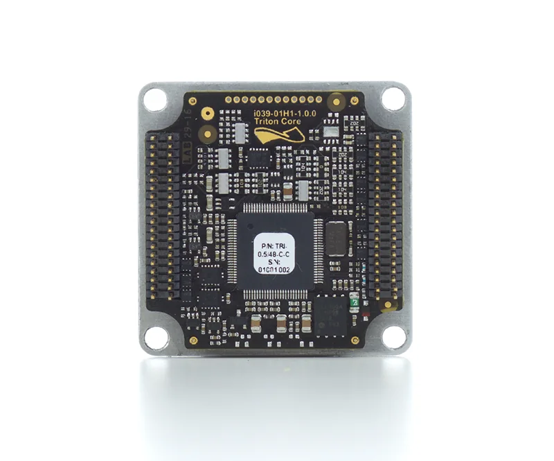
A servo driver PCB assembly is difficult to manufacture because the board combines high-current switching, sensitive feedback measurement, control electronics, communications, thermal interfaces, and safety-related isolation in one assembly.
The production challenge is not only building the PCB correctly. The manufacturer must preserve the electrical intent of the design while knowing exactly how to place components, control soldering, inspect hidden joints, program firmware, and verify operation under realistic conditions.
Key takeaways
- Release the power stage, gate-drive loops, sensing references, isolation boundaries, thermal interfaces, and test access together.
- Define exposed-pad solder requirements, connector processes, approved substitutions, and inspection limits before the first build.
- Match inspection and functional testing to the failure modes that matter: switching damage, thermal failure, feedback errors, and intermittent field faults.
- Include firmware, calibration, fixture requirements, and production limits in the assembly package.
- A board that passes continuity or basic electrical checks may still fail during switching, motor loading, regeneration, temperature cycling, or EMC testing.
What makes a servo driver PCB assembly different from a standard PCBA?
Servo drivers combine multiple electrical environments on the same board.
| Functional zone | Main assembly or layout risk | Release evidence |
|---|---|---|
| DC link and inverter bridge | Current concentration, switching loop inductance, copper heating | Current-path review and thermal evidence |
| Gate driver | Excess loop area, ringing, false turn-on | Layout review and switching waveform data |
| Current sensing | Kelvin routing errors, reference noise, polarity mistakes | Calibration plan and measurement limits |
| Isolation boundary | Incorrect spacing, contamination, wrong components | Controlled drawing and safety requirements |
| Encoder/feedback | Noise coupling, shield errors, connector mistakes | Interface specification and noise testing |
| Control electronics | Firmware mismatch, ground bounce, communication faults | Version-controlled firmware and functional test |
| Thermal interface | Poor paste coverage, voiding, mechanical mismatch | X-ray criteria and thermal verification |
The correct manufacturing approach depends on the power devices used, including MOSFET, IGBT, silicon carbide, or gallium nitride devices. The assembly package must identify approved parts and applicable manufacturer guidance.
What information should be frozen before servo driver PCB assembly?
A production handoff should answer four questions:
- What is being built?
- How should it be assembled?
- How should it be inspected?
- How should it be tested?
The release package should include:
- fabrication outputs, stackup, impedance requirements, and drill data;
- BOM with approved manufacturers, alternates, and do-not-substitute components;
- centroid data and assembly drawings;
- polarity, orientation, connector, and mechanical notes;
- firmware image, programming instructions, and configuration data;
- calibration constants and acceptance limits;
- fixture requirements and test procedures.
The electrical design intent must also be documented. A BOM alone does not explain why a gate resistor, current shunt, capacitor placement, or isolation component was selected.
How should the power stage and gate driver be handed off?
The power stage should be reviewed around the actual current paths.
Confirm:
- DC-link capacitor placement relative to switching devices.
- High-current commutation loop size and return path.
- Gate-driver distance from the power switch.
- Gate and return routing, including Kelvin source or emitter connections.
- Switching-node copper coupling into sensing and control areas.
- Current-sense routing and reference points.
- Isolation slots, creepage, clearance, and coating boundaries.
- Connector phase order, shield termination, and chassis strategy.
Creepage and clearance requirements depend on working voltage, transient category, pollution degree, material group, altitude, coating system, and the applicable product standard. A generic spacing value copied from another design does not replace product-specific evaluation.
Which servo driver assembly decisions need supplier agreement?
| Decision area | Supplier input required | Evidence before production |
|---|---|---|
| Power package soldering | Stencil design, paste volume, reflow capability | Process review and sample inspection |
| Thermal pad attachment | Aperture pattern, void criteria, seating requirements | X-ray or validated inspection method |
| High-current connectors | Solder sequence, mechanical support, thermal profile | Assembly drawing and inspection record |
| Programming | Firmware handling and fixture interface | Program verification record |
| Functional test | Fixture, load method, safety controls | Approved test procedure and limits |
| Traceability | Serial records and material tracking | Production history report |
How do stencil and solder controls affect servo driver reliability?
Large exposed thermal pads require controlled paste design. The aperture strategy affects solder volume, package seating, thermal performance, and mechanical stability.
The assembly package should define:
- manufacturer land pattern requirements;
- stencil thickness and aperture approach;
- solder alloy and process window;
- acceptable voiding criteria where applicable;
- component height and coplanarity limits;
- through-hole connector solder requirements;
- cleaning, coating, masking, and contamination controls.
The PCB stencil and turnkey assembly pages describe related manufacturing capabilities. Final process settings should be approved against the actual package, board construction, and inspection plan.
Which inspection and test method should be selected?
Each method answers a different production question.
| Method | Detects well | Does not prove by itself |
|---|---|---|
| SPI | Paste volume, height, area, offset | Electrical performance |
| AOI | Placement, polarity, visible solder issues | Hidden thermal-pad quality |
| X-ray | Hidden solder distribution, bridges, voiding | Switching behavior |
| Electrical test | Opens, shorts, selected component checks | Firmware or load operation |
| Low-voltage powered test | Rails, communication, basic I/O | Full-power switching |
| Functional/load test | Control response, protection, current behavior | Every field condition |
The correct test plan begins with failure modes.
What is the recommended servo driver functional-test sequence?
A controlled sequence reduces damage and improves diagnosis.
- Verify revision, BOM, polarity, solder quality, cleanliness, and mechanical fit.
- Measure resistance and critical nets before applying energy.
- Power auxiliary rails from a controlled source.
- Verify clocks, resets, communications, programming, and configuration.
- Check gate-drive supplies, dead-time behavior, current-sense offset, encoder signals, and protection inputs.
- Apply controlled DC-bus energy after low-energy checks pass.
- Test with an approved motor or load while monitoring current, temperature, and protection behavior.
- Record results against production limits.
Hi-pot, insulation resistance, protective-earth, and partial-discharge testing should only be applied when required by the product design and with validated limits.
What are common servo driver PCBA failures and how are they diagnosed?
| Symptom | Possible cause | Evidence to capture |
|---|---|---|
| Switch failure or false turn-on | Gate loop inductance, Miller coupling, poor return path | Gate waveform and layout review |
| Current instability | Sense routing, calibration error, wrong shunt, solder issue | ADC data and inspection results |
| Encoder faults during operation | Cable noise, shielding, connector errors | Interface waveform during switching |
| Overtemperature | Thermal pad issue, copper limitation, switching loss | X-ray, thermal image, mechanical review |
| Connector failure | Weak solder joint, mechanical stress, process issue | Joint inspection and load review |
| Field-only failures | Installation, grounding, airflow, regeneration effects | System event records |
What should be included in a servo driver PCB assembly RFQ package?
A complete supplier package includes:
- Gerber or ODB++, drill, netlist, stackup, and impedance information;
- BOM with approved sources and substitutions;
- assembly drawings and 3D models;
- power-device, gate-driver, sensing, connector, and thermal requirements;
- stencil and inspection requirements;
- firmware and programming instructions;
- calibration procedure and pass/fail limits;
- maximum test energy and discharge requirements;
- traceability expectations;
- first-article, inspection, and test-data requirements.
The DFM guidelines and testing and quality resources provide additional structure for production preparation.
FAQ
What files are most often missing from a servo driver PCBA handoff?
Firmware, approved alternates, thermal-interface requirements, connector definitions, fixture information, calibration data, and production test limits are frequently missing even when Gerbers and BOM files are available.
Does X-ray inspection prove a power stage will operate reliably?
No. X-ray verifies hidden assembly conditions such as solder distribution and voiding. Switching performance, thermal behavior, protection circuits, and motor operation require electrical and functional validation.
Should every servo driver use identical gate-drive settings?
No. Gate resistance, switching speed, layout, device characteristics, bus voltage, parasitics, thermal limits, and EMC requirements determine the appropriate design.
Can functional testing be added after layout completion?
Some testing can be added later, but missing access to programming points, measurement nodes, and fixture interfaces increases cost and reduces diagnostic coverage.
Does IPC workmanship acceptance qualify the complete servo drive?
No. IPC standards address assembly workmanship. Product safety, EMC compliance, reliability testing, and application qualification remain separate requirements.
Make the first powered servo driver predictable
Servo driver PCB assembly succeeds when electrical intent, manufacturing controls, inspection strategy, firmware, and functional testing are released as one controlled package. A complete handoff lets the supplier build, inspect, diagnose, and repeat production without relying on undocumented assumptions.