Contents
- The Context: What Makes Side Radar PCB Challenging
- The Core Technologies (What Actually Makes It Work)
- Ecosystem View: Related Boards / Interfaces / Manufacturing Steps
- Comparison: Common Options and What You Gain / Lose
- Reliability & Performance Pillars (Signal / Power / Thermal / Process Control)
- The Future: Where This Is Going (Materials, Integration, Ai/automation)
- Request a Quote / DFM Review for Side Radar PCB (What to Send)
- Conclusion
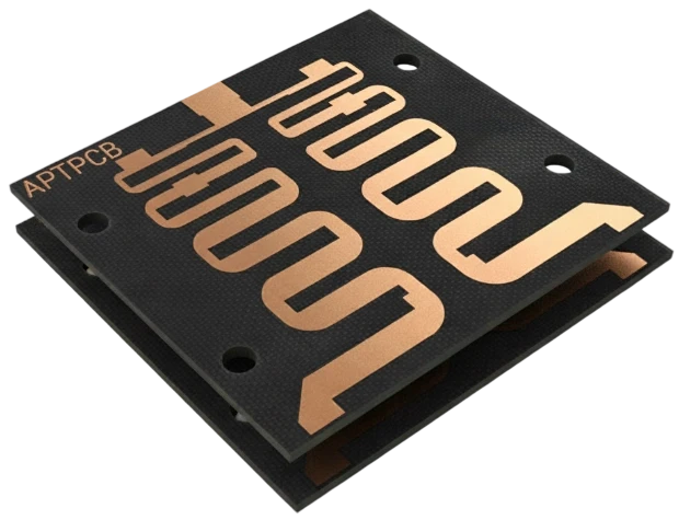
A Side Radar PCB is a specialized printed circuit board designed to host radio frequency (RF) transceivers and antenna arrays operating typically at 24GHz, 77GHz, or 79GHz. Unlike standard control boards, these PCBs act as active components in the RF signal chain; the copper etching itself forms the antenna elements. A "good" Side Radar PCB is defined by its ability to maintain low insertion loss, consistent dielectric properties across wide temperature ranges (-40°C to +125°C), and structural integrity under constant vibration, ensuring the vehicle "sees" its surroundings accurately for its entire lifespan.
Highlights
- Frequency Shift: The industry is migrating from 24GHz (narrow bandwidth) to 77GHz/79GHz (high resolution), requiring tighter manufacturing tolerances.
- Hybrid Stackups: To balance performance and cost, most side radars utilize a hybrid build—high-frequency laminates for the RF layer and standard FR4 for digital control layers.
- Etching Precision: At 77GHz, a trace width variation of just 10 microns can significantly alter antenna impedance and beam shape.
- Surface Finish Sensitivity: The skin effect at millimeter-wave frequencies makes the choice of surface finish (e.g., Immersion Silver vs. ENIG) critical for signal integrity.
- Thermal Management: Compact, sealed housings require efficient heat dissipation paths directly through the PCB structure.
The Context: What Makes Side Radar PCB Challenging
The engineering environment for Side Radar PCBs is defined by a conflict between physics and economics. While a front-facing long-range radar is a premium component where performance is paramount, side radars are often deployed in pairs (rear corners) or quads (all four corners). This multiplication factor exerts immense pressure on the bill of materials (BOM). Manufacturers cannot simply use the most expensive ceramic-filled PTFE materials for the entire board stackup without blowing the budget.
Furthermore, the physical location of these sensors introduces unique constraints. Side radars are typically mounted inside bumpers or side mirrors. They do not have the luxury of a clear line of sight; they must transmit through the vehicle's fascia (bumper plastic and paint), which acts as a radome. The PCB design must account for the signal attenuation caused by the bumper. Any inconsistency in the PCB's output power or phase accuracy complicates the calibration required to compensate for the bumper's interference.
At APTPCB (APTPCB PCB Factory), we observe that the transition to 77GHz and 79GHz bands has dramatically reduced the margin for error. The wavelength at 77GHz is approximately 3.9mm. Antenna patch elements are fractions of this size. Consequently, standard PCB manufacturing tolerances (e.g., ±20% on trace width) are unacceptable. The challenge lies in achieving "semiconductor-like" precision on a large-format PCB manufacturing floor, ensuring that the radar module on the left bumper performs identically to the one on the right.
The Core Technologies (What Actually Makes It Work)
To meet the stringent requirements of millimeter-wave radar, Side Radar PCBs rely on a specific set of technologies that differentiate them from standard automotive electronics.
1. Hybrid Layer Stackups
The most defining characteristic of a modern Side Radar PCB is the hybrid stackup. A typical 4-layer or 6-layer board will use a high-performance high-frequency laminate (such as Rogers RO3003, RO4350B, or Isola Astra MT77) for the top layer where the RF signals travel. The layers below, which handle power distribution and digital communication (CAN-FD or Automotive Ethernet), are made from standard high-Tg FR4.
- The Benefit: This approach significantly reduces material costs compared to a full-PTFE board while maintaining RF performance where it counts.
- The Challenge: Bonding dissimilar materials requires expertise. PTFE and FR4 have different coefficients of thermal expansion (CTE) and require different lamination cycles. If not managed correctly during the PCB stack-up design and pressing process, the board can warp or delaminate during reflow soldering.
2. Precision Antenna Etching
The antenna array—usually a series of patch antennas or a slotted waveguide—is etched directly into the top copper layer. At 77GHz, the "skin depth" (where the current flows) is extremely shallow.
- Line Width Control: Manufacturers must use advanced laser direct imaging (LDI) and vacuum etching processes to keep trace width tolerances within ±10μm or better.
- Copper Profile: The roughness of the copper foil matters. Standard copper is too rough for 77GHz signals, acting like a mountain range that slows down the wave. Side Radar PCBs use Very Low Profile (VLP) or Reverse Treated Foil (RTF) copper to minimize insertion loss.
3. Micro-via Technology
Connecting the top RF layer to the inner ground planes requires low-inductance pathways. Laser-drilled micro-vias are essential here. They provide the shortest possible path to ground, minimizing parasitic inductance that could distort the high-frequency signal. In HDI PCB designs for radar, these vias are often filled and plated over (via-in-pad) to allow components to be mounted directly on top, saving critical space.
4. Cavity Structures (Optional)
In some advanced designs, the MMIC (Monolithic Microwave Integrated Circuit) is placed in a recessed cavity within the PCB. This shortens the bond wire length between the chip and the board, reducing inductance and improving signal transfer efficiency. While more expensive to manufacture, this technique is becoming relevant for high-performance 4D imaging radars.
Ecosystem View: Related Boards / Interfaces / Manufacturing Steps
A Side Radar PCB does not exist in a vacuum; it is part of a tightly integrated ecosystem involving mechanical housing, thermal interfaces, and downstream assembly.
The Interface with Assembly (PCBA): The assembly process for these boards is unforgiving. The radar MMIC is typically a BGA (Ball Grid Array) or QFN (Quad Flat No-lead) package with a fine pitch. Because the board uses a hybrid stackup, the thermal profile during reflow must be carefully tuned to ensure both the ceramic-filled laminate and the FR4 cure properly without warping. SMT assembly lines must also handle the board gently to avoid scratching the antenna areas, as a scratch on a patch antenna can permanently alter its resonant frequency.
Thermal Interface Materials (TIM): Radar chips generate significant heat, and because the module is sealed against moisture (IP67/IP69K), there is no airflow. The PCB must act as a heat spreader. Designers often employ dense arrays of thermal vias under the MMIC to conduct heat to a metal backing or the aluminum housing. In some cases, Metal Core PCBs or heavy copper layers are utilized, though hybrid FR4/RF laminates remain the standard for side radar due to their superior RF properties compared to standard IMS (Insulated Metal Substrate).
Testing and Calibration: Once assembled, the Side Radar PCB undergoes rigorous End-of-Line (EOL) testing. This involves placing the module in an anechoic chamber to verify the antenna pattern. If the PCB manufacturing tolerances drifted—for example, if the dielectric thickness varied by 5%—the beam angle might shift, causing the radar to misjudge the position of an object. This highlights why process control at the bare board level is directly linked to the safety rating of the final vehicle.
Comparison: Common Options and What You Gain / Lose
When specifying a Side Radar PCB, engineers often face choices regarding material selection and surface finishes. The trade-offs usually revolve around signal integrity versus cost and durability.
The choice of surface finish is particularly contentious. HASL (Hot Air Solder Leveling) is never used because the uneven surface disrupts the planar nature of the antenna. The debate is usually between Electroless Nickel Immersion Gold (ENIG) and Immersion Silver (ImAg). ENIG is robust but the nickel layer has magnetic properties that can cause insertion loss at high frequencies. Immersion Silver is excellent for RF but can tarnish if not handled properly.
Decision Matrix: Technical Choice → Practical Outcome
| Technical choice | Direct impact |
|---|---|
| Material: Pure PTFE (e.g., Rogers RO3003) | Best RF performance and stability; highest cost and difficult mechanical processing (soft material). |
| Material: Hybrid (PTFE + FR4) | Balanced cost/performance; standard for mass-market side radars; requires complex lamination cycles. |
| Finish: Immersion Silver (ImAg) | Lowest insertion loss (no nickel); sensitive to handling and sulfur environments (requires careful storage). |
| Finish: ENIG (Nickel/Gold) | Excellent shelf life and solderability; higher insertion loss at >70GHz due to nickel skin effect. |
Reliability & Performance Pillars (Signal / Power / Thermal / Process Control)
Reliability in automotive radar is non-negotiable. A failure in a side radar could mean a vehicle changes lanes into occupied space. APTPCB emphasizes four pillars of reliability for these components.
1. Signal Integrity (Dk/Df Stability) The Dielectric Constant (Dk) of the laminate must remain stable across the operating temperature range. If the Dk shifts as the car heats up in the sun, the radar's frequency will drift. We verify materials using IPC-TM-650 test methods to ensure the Dk tolerance is within ±0.05.
2. Dimensional Stability (Etch Factor) As mentioned, the geometry of the antenna patch determines the beam shape. We utilize automated optical inspection (AOI) specifically tuned for RF features to measure trace widths. The "etch factor"—the ratio of downward etch to sideways etch—must be compensated for in the CAM engineering stage to ensure the final copper trapezoid matches the simulation.
3. Thermal Reliability Side radars are subjected to thermal shock. The vias connecting the RF layer to the ground plane must withstand thousands of cycles of expansion and contraction. We perform interconnect stress testing (IST) to verify the integrity of the copper plating in the barrel of the via.
4. Environmental Protection Since Immersion Silver is common, the board must be free of ionic contamination before coating. We employ strict cleaning processes and often recommend conformal coating during assembly to protect the exposed silver from oxidation and sulfur attack over the vehicle's 15-year life.
| Feature | Standard PCB Tolerance | Side Radar PCB Requirement |
|---|---|---|
| Trace Width | ±20% | ±10% or ±10μm (whichever is tighter) |
| Dielectric Thickness | ±10% | ±5% |
| Surface Roughness | Standard Foil | VLP / HVLP (Ra < 0.5μm) |
| Solder Mask Registration | ±50μm | ±25μm (critical near antenna patches) |
The Future: Where This Is Going (Materials, Integration, Ai/automation)
The evolution of Side Radar PCBs is being driven by the demand for "4D" sensing—adding elevation to the existing range, azimuth, and velocity data. This requires more antenna channels (MIMO arrays), which pushes board density higher. We are seeing a shift toward multi-layer RF structures where multiple high-frequency layers are bonded together, moving beyond the simple "one RF layer on top" hybrid stackup.
Additionally, the industry is exploring "Antenna-in-Package" (AiP) technologies, where the antenna is integrated directly into the chip package. However, for the foreseeable future, PCB-based antennas remain the most cost-effective solution for achieving the necessary gain and aperture size for medium-range detection.
5-Year Performance Trajectory (Illustrative)
| Performance metric | Today (typical) | 5-year direction | Why it matters |
|---|---|---|---|
| **Operating Frequency** | 76-77 GHz | 77-81 GHz (Wideband) | Wider bandwidth enables higher resolution for separating closely spaced objects. |
| **Layer Count** | 4-6 Layers (Hybrid) | 8-12 Layers (HDI Hybrid) | Supports complex MIMO antenna arrays for 4D imaging capabilities. |
| **Material Technology** | Ceramic-filled PTFE | Glass-free / PPE blends | Further reduction of Df (dissipation factor) to minimize signal loss at >80GHz. |
Request a Quote / DFM Review for Side Radar PCB (What to Send)
When engaging a manufacturer for Side Radar PCBs, clarity on RF requirements is as important as the Gerber files. A standard PCB quote package is often insufficient because it lacks the specific material and tolerance data needed for millimeter-wave performance. To get an accurate quote and a meaningful Design for Manufacturing (DFM) review, ensure your package includes the following:
- Specific Material Callouts: Do not just say "High Frequency Material." Specify the exact laminate (e.g., "Rogers RO3003 5mil" or "Isola Astra MT77"). If equivalents are allowed, state the required Dk and Df values explicitly.
- Hybrid Stackup Detail: Clearly define which layers are RF (high frequency) and which are digital (FR4). Provide a stackup drawing showing the arrangement of prepreg and core.
- Antenna Layer Tolerances: Highlight the antenna features in the Gerber files and specify the required line width tolerance (e.g., ±15μm).
- Surface Finish: Specify Immersion Silver, ENIG, or ENEPIG, and note if there are any "keep out" areas for solder mask near the antenna elements.
- Copper Profile: If VLP or HVLP copper is required, this must be stated in the fabrication notes.
- Testing Requirements: Indicate if TDR (impedance) testing or specific insertion loss testing is required on coupons or production boards.
- Volume and Lead Time: Prototype quantities (5-50) vs. production forecasts, as this affects material procurement strategies.
Conclusion
Side Radar PCBs represent a critical intersection of advanced material science and high-volume manufacturing. They are no longer niche components reserved for luxury vehicles; they are the standard eyes and ears of modern automotive safety systems. The shift to 77GHz and the demand for higher resolution impose strict requirements on etching precision, material stability, and layer registration that go far beyond standard PCB fabrication.
Success in this domain requires a partnership with a manufacturer who understands that a PCB is not just a carrier for components, but an active part of the RF circuit. By carefully selecting hybrid stackups, defining precise tolerances, and validating performance through rigorous testing, engineers can deploy reliable, high-performance radar systems that enhance safety on the road. For those ready to move from simulation to physical reality, APTPCB offers the specialized capabilities and engineering support needed to navigate the complexities of millimeter-wave PCB fabrication.