
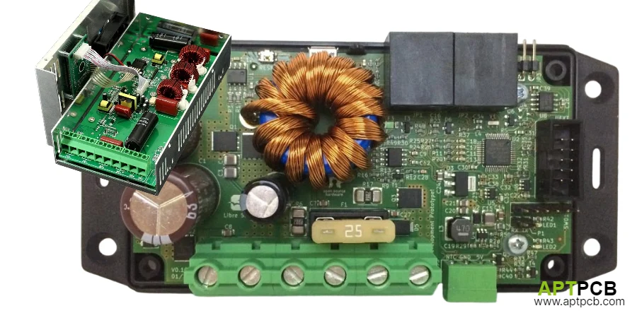
Solar charge controller PCB assemblies manage the power transfer between photovoltaic panels, batteries, and connected loads. The PCBA must regulate charging current, protect battery cells, control loads, and maintain reliable operation in environments ranging from indoor energy storage cabinets to outdoor solar installations.
For RV systems, marine electronics, telecom backup power, remote monitoring stations, and residential off-grid systems, the PCB assembly decision directly affects efficiency, product lifetime, and field reliability.
A solar controller manufacturer must evaluate more than SMT assembly capability. The right production partner should understand power electronics layout, battery charging algorithms, thermal constraints, environmental protection, and functional testing requirements.
APTPCB supports solar charge controller assembly for PWM, MPPT, and hybrid charging platforms, including prototype development, component sourcing, testing, and volume manufacturing.
What PCB Assembly Requirements Matter Most for Solar Charge Controllers?
A reliable solar controller PCBA must balance electrical performance, protection, and manufacturing consistency.
The main engineering decisions include:
- Selecting PWM or MPPT charging architecture.
- Designing the power switching stage for current and thermal limits.
- Supporting the required battery chemistry.
- Protecting against electrical faults.
- Controlling EMI from high-frequency switching.
- Validating operation through functional testing.
The PCB assembly supplier should understand how component selection, PCB layout, and manufacturing processes influence long-term product reliability.
Should You Choose PWM or MPPT Solar Charge Controller PCB Assembly?
The charging topology determines PCB complexity, component requirements, and production cost.
| Requirement | PWM Controller PCB | MPPT Controller PCB |
|---|---|---|
| Circuit complexity | Lower complexity | Higher complexity |
| Typical PCB layers | 2–4 layers | 6–8 layers commonly used |
| Main focus | Reliable switching and cost optimization | Power conversion efficiency and control accuracy |
| Power stage | MOSFET switching control | Advanced DC-DC conversion topology |
| Measurement requirements | Basic voltage/current monitoring | Precision voltage, current, and temperature sensing |
| Thermal challenge | Moderate | Higher due to switching losses |
| Application examples | Small off-grid systems | Higher efficiency residential and commercial systems |
A PWM design is often selected when cost, simplicity, and reliability are the primary goals. MPPT designs are preferred when maximizing harvested solar energy is more important and the additional power electronics complexity is justified.
How Does MPPT vs PWM Selection Affect PCB Design Decisions?
The topology choice changes the assembly requirements.
| Decision Factor | PWM Design | MPPT Design |
|---|---|---|
| Power conversion | Direct battery charging control | DC-DC conversion stage |
| Switching requirements | Lower frequency switching | High-frequency switching commonly 50–300 kHz |
| PCB layout priority | Current handling and reliability | Power loop control, EMI reduction, thermal management |
| Control system | Simpler voltage thresholds | Advanced tracking algorithms and precision sensing |
| Component demand | Fewer power components | MOSFETs, inductors, gate drivers, sensing circuits |
| Assembly complexity | Lower | Higher |
MPPT controllers require careful placement of MOSFETs, inductors, current sensors, and control ICs. High-current switching loops should be minimized to reduce EMI and switching losses.
How Does Battery Management Improve Solar Controller PCBA Reliability?
Solar charge controllers must support different battery technologies including flooded lead-acid, AGM, gel, lithium-ion, and LiFePO4 batteries.
Incorrect charging parameters can reduce battery capacity, shorten service life, or create safety concerns.
Essential Battery Charging Functions
- Multi-Stage Charging: Turnkey assembly supporting bulk, absorption, float, and equalization charging stages.
- Voltage Regulation Accuracy: Feedback circuits maintaining stable charging voltage.
- Current Limiting: Protection against excessive charging current.
- Temperature Compensation: Adjustment of charging parameters based on battery temperature.
- Battery Chemistry Selection: Configurable charging profiles for different battery technologies.
- Reverse Polarity Protection: MOSFET or diode protection preventing installation damage.
For lithium battery applications, the controller design should also coordinate with battery management systems where required.
What Protection Circuits Should a Solar Charge Controller PCBA Include?
Protection design determines how well the controller survives abnormal operating conditions.
| Failure Mode | Typical Cause | PCB Design Response |
|---|---|---|
| Battery overcharge | Incorrect voltage regulation | Precision feedback circuits and firmware limits |
| Deep battery discharge | Poor load management | Low-voltage disconnect protection |
| MOSFET overheating | Excess current or insufficient cooling | Thermal design and component derating |
| Reverse connection damage | Installation error | Reverse polarity protection |
| Communication failure | Noise or poor signal routing | Interface protection and validation testing |
| Outdoor corrosion | Moisture exposure | Conformal coating and environmental protection |
A production supplier should verify these protections through functional testing instead of relying only on visual inspection.
How Should Solar Controller PCBs Handle Load Management?
Many solar controllers provide load outputs for lighting systems, monitoring equipment, and DC appliances.
Important load-control functions include:
- Load Switching Integration: MOSFET switching designed for low voltage loss.
- Low-Voltage Disconnect: Battery protection thresholds with controlled reconnect behavior.
- Load Reconnect Logic: Automatic restoration after battery recovery.
- Timer Functions: Scheduled operation for lighting and remote applications.
- Current Monitoring: Load measurement and overcurrent protection.
- Manual Override: User-controlled operation when required.
Combining charging control and load management improves battery protection and system availability.
What Environmental Protection Does an Outdoor Solar PCBA Need?
Solar controllers installed outdoors face humidity, temperature cycling, dust, vibration, and sunlight exposure.
Outdoor Solar PCBA Protection Requirements
- Conformal Coating Application: PCB conformal coating protecting against humidity, contamination, and corrosion.
- Industrial Components: Components selected for extended temperature operation such as -40°C to +70°C environments.
- Thermal Management: Heat dissipation strategies preventing excessive temperature rise inside sealed enclosures.
- Connector Protection: Reliable connectors designed for environmental exposure.
- UV Resistance: Materials selected for long-term sunlight exposure.
- Vibration Resistance: Mechanical design supporting field operation.
Through environmental protection and special PCB manufacturing, solar controller assemblies can achieve dependable long-term operation.
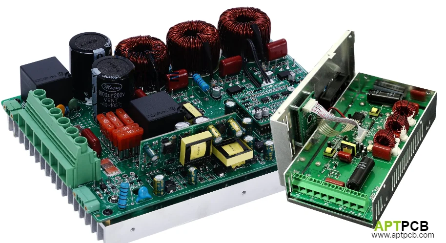
Which Tests Should Validate Solar Charge Controller PCB Assembly Quality?
Testing should confirm charging behavior, protection response, communication functions, and production consistency.
| Test Area | Validation Goal |
|---|---|
| Charging algorithm test | Confirm charging stages and battery profiles |
| Voltage/current regulation | Verify control accuracy |
| Protection testing | Confirm overvoltage, overcurrent, thermal, and reverse polarity response |
| Load switching test | Validate MOSFET operation and current handling |
| Temperature testing | Confirm compensation performance |
| Communication test | Verify RS-485, Modbus, CAN, or wireless interfaces |
| Burn-in testing | Detect early component failures |
APTPCB supports production validation and functional testing processes to verify complete controller operation before shipment.
How Do You Select a Solar Charge Controller PCB Assembly Supplier?
Supplier selection should evaluate engineering capability, manufacturing control, and lifecycle support.
Solar PCBA Supplier Qualification Checklist
| Evaluation Item | Supplier Requirement |
|---|---|
| Power electronics experience | Experience with charging, battery, and energy applications |
| Assembly capability | SMT, THT, and turnkey production support |
| Component sourcing | Supply chain control for critical MOSFETs and ICs |
| Testing capability | Functional testing and reliability validation |
| Environmental capability | Coating and outdoor protection experience |
| Production scalability | Prototype through volume manufacturing support |
| Documentation | Traceability, inspection records, and quality reports |
A qualified supplier should provide manufacturing records, component traceability, inspection data, and support throughout product development.
How Does APTPCB Support Solar Charge Controller Manufacturing?
Solar controller manufacturers need flexible support from engineering validation to high-volume production.
APTPCB provides:
- Rapid Prototyping: NPI assembly supporting prototype validation and design improvement.
- Custom Configurations: PCB assembly for different power ratings, interfaces, and battery systems.
- Volume Manufacturing: Mass production supporting consistent large-scale output.
- Component Management: Component sourcing for power semiconductors, controllers, sensors, and specialized components.
- Certification Support: Manufacturing documentation supporting UL, CE, and regional compliance processes.
- Engineering Support: Design optimization, manufacturing review, and test development assistance.
With experience in power energy PCB applications, APTPCB helps solar product companies develop reliable charging solutions for residential, commercial, and industrial markets.
Conclusion: Build Reliable Solar Charge Controller PCB Assemblies
A successful solar charge controller PCBA requires coordinated decisions across topology selection, PCB design, battery management, protection circuits, environmental protection, and manufacturing validation.
PWM and MPPT systems require different assembly approaches, but both depend on accurate engineering, reliable components, and disciplined production testing.
Selecting a supplier with power electronics experience helps reduce redesign cycles, improve product reliability, and deliver solar charging systems ready for demanding real-world applications.