
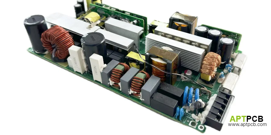
Solar inverter PCB assembly rarely means one generic board. Most projects split the hardware into at least a power section, a control or monitoring section, and the connector or harness handoff that ties the assembly into the larger enclosure. That split is the useful starting point for both fabrication and assembly review.
If your project is still comparing suppliers, start with the power and energy PCB page. If the main risk is heat removal rather than topology, route the stack-up discussion early to high-thermal PCB. If the question is how the finished assembly gets verified after build, keep FCT test in scope from the beginning instead of adding it late.
Keep the review at the board and PCBA boundary: partitioning, isolation-aware layout zones, thermal route choices, manufacturability review, and assembly or test handoff. It does not prove inverter efficiency, standards compliance, or field life.
Quick Answer A solar inverter power PCB should be reviewed as a managed power assembly before release: separate the noisy power stage from control and monitoring, lock the isolation-aware interface plan, define the thermal route, and specify how the populated board will be assembled and powered for verification. If those boundaries stay implicit, small release-package gaps become blocked inspection views, unsafe or inconsistent bring-up setups, and late mechanical rework during pilot build.
Table of Contents
- 1. What a Solar Inverter Power PCB Usually Includes
- 2. Where to Split the Power Board from Control and Monitoring
- 3. How to Review the Thermal Route Before Fabrication
- 4. What Manufacturing Review Should Catch Early
- 5. How to Plan Assembly and Functional-Test Handoff
- Conclusion: Release the Board as a Managed Power Assembly
1. What a Solar Inverter Power PCB Usually Includes
In practice, a solar inverter build often contains more than one board role:
- a power stage carrying the noisy switching path
- a control board handling logic, sensing, and communication
- support boards for monitoring, gate drive, or front-panel and connector functions
Treating those roles separately helps more than calling everything a "high-power PCB." The manufacturing questions are different for each section. The power stage is dominated by copper distribution, thermal exit path, component spacing strategy, and bus or cable entry. The control section is dominated by noise separation, connector planning, test access, and stable assembly around fine-pitch devices.
For the power stage, the bare board is often a heavy copper PCB manufacturer job: 3 oz or heavier copper for bus currents, wide spacing, and plated holes sized for large terminals. The control section is usually a conventional multilayer build. Quoting them as separate board families keeps the fabrication route honest.
2. Where to Split the Power Board from Control and Monitoring
For inverter hardware, the safest layout review question is not "how much power does this board handle?" It is "which area is noisy, which area is sensitive, and where does the interface between them actually live?"
Useful review points include:
- keep the switching power stage compact so transient current stays local
- avoid mixing small-signal control routing into noisy copper regions
- place local input and decoupling parts close to the relevant power loop
- define the boundary between the main power path and the sensing or controller circuitry
- freeze connector, bus bar, and harness entry directions before panelization and fixture planning
That partitioning matters for manufacturing because mechanical decisions follow it. Mounting holes, heatsink interfaces, connector reinforcement, and keep-clear areas all depend on where the power section stops and the control section begins.
When projects skip this step, the result is usually not a theoretical electrical problem first. It is a release problem: unclear assembly sequence, awkward cable routing, blocked inspection views, or test access that disappears after the enclosure team locks the mechanical stack.
That is the main failure chain for this topic: the board leaves layout review with only broad inverter intent; assembly, enclosure, and test teams each interpret connector exits, barrier zones, and heatsink attachment differently; the first build then arrives with missing access, unclear fixture assumptions, or unresolved hardware order; and the program burns time on rework because the release package did not turn those boundaries into explicit manufacturing instructions.
3. How to Review the Thermal Route Before Fabrication
Thermal planning for a solar inverter power PCB should be treated as a route, not a material label. A board may use heavier copper, a thermally oriented stack-up, an insulated metal route, or a conventional structure that transfers heat into external metalwork. Those are different choices and should not be collapsed into one default answer.
Before fabrication, confirm:
- where the main heat sources sit on the board
- whether heat is expected to spread laterally in copper, vertically through the stack, or directly into a heatsink or chassis
- whether the chosen substrate still supports the isolation and routing needs of the design
- whether mounting pressure, flatness, interface material, and fastener access have been defined
- whether assembly can still inspect and clean the board after the thermal hardware is added
If the project clearly depends on board-level heat transfer, move the thermal-substrate discussion forward early. That is more useful than arguing in general terms about whether heavy copper or metal-core construction is "better." They are route choices tied to the heat path and the assembly method.
4. What Manufacturing Review Should Catch Early
A solar inverter power board usually needs a tighter review package than a generic industrial control board because the assembly mixes power parts, connectors, mechanical interfaces, and later test requirements.
The most useful DFM review checks are usually:
Board family split Confirm which files belong to the power stage, which belong to control or monitoring, and which subassemblies may need separate build or inspection flow.
Copper and termination strategy Freeze whether current handoff happens through soldered terminals, press-fit or bolted hardware, bus bars, or harness connectors. That decision affects hole design, reinforcement, and assembly sequence.
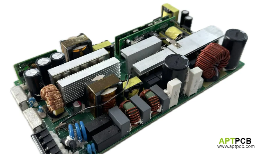
On inverter main boards, this point is more dangerous than it looks. The layout often uses 3 oz or 4 oz copper and mixes very large THT parts such as IGBTs, common-mode chokes, and heavy terminal blocks. To maximize current capacity, some designs connect those pins directly into large internal copper pours with no thermal-relief spokes at all. In CAD, that looks electrically strong. In wave soldering or selective soldering, it becomes a heat-extraction problem.
The heavy copper plane behaves like a massive heatsink and pulls energy away from the joint before the solder can climb the barrel by capillary action. The result is a hidden cold joint or barrel fill well below 50 percent, even though the solder fillet on the visible side may look acceptable. Factory testing at room temperature may still pass. In the field, under peak solar harvest and current above 100 A, that high-resistance joint starts heating itself, loses wetting integrity, and can desolder under load. The end state is not a minor reliability drift. It can become internal arcing and board meltdown inside the inverter. That is why inverter review cannot stop at copper weight. Thermal-relief design and barrel-fill DFM for high-thermal-mass THT joints are part of the fire boundary.
Isolation-aware keepouts Do not leave slots, barriers, edge spacing, or connector separation as implied intent. They should be explicit in the release package without turning the article into a standards or compliance claim.
Thermal hardware access Review screw heads, clips, thermal pads, standoffs, and heatsink contact areas before tooling and fixture plans are frozen.
Mixed component process Decide early whether the build includes only SMT, or a mixed SMT plus THT route with selective manual steps, secondary fastening, or coating masks.
Inspection visibility Make sure key solder joints, terminals, and heat-loaded components remain inspectable after shields, bars, or mechanical brackets are installed.
5. How to Plan Assembly and Functional-Test Handoff
What does solar inverter PCB assembly involve?
| Assembly stage | Power stage | Control and monitoring board | What to agree before release |
|---|---|---|---|
| SMT | Gate drivers, sense resistors, small passives | MCU/DSP, communication, fine-pitch ICs | Stencil and paste plan around large thermal pads |
| THT and press-fit | IGBT or MOSFET modules, chokes, terminal blocks, bus connections | Headers and board-to-board connectors | Wave, selective, or manual route; thermal relief on heavy-copper pins |
| Mechanical | Heatsinks, clips, standoffs, bus bars | Shields, brackets | Fastener sequence and torque; inspection access after fitting |
| Coating (if required) | Masking around terminals and heatsink faces | Masking around connectors and test points | Coating areas and keep-outs on the drawing |
| Inspection | X-ray or cross-section on high-mass THT joints where barrel fill matters | AOI on fine-pitch areas | Which joints get which method |
| Powered test | Safe bring-up at reduced voltage before full power | Firmware load, interface checks | Test limits and fixture ownership |
Mixed SMT and THT power boards are a standard SMT and THT assembly route, but only if the heavy-copper THT joints are designed for the chosen soldering method.
For this type of board, assembly and test planning should start while the layout is still adjustable. The core question is whether the finished build can be powered, connected, and observed in a controlled way after soldering and final mechanical attachment.
Good handoff planning usually includes:
- fixture access for board power-up and safe connector engagement
- clear labeling for harness orientation and variant control
- test points or alternate access on the control section where direct probing is limited
- agreement on which items are verified in bare-board electrical test, inline inspection, and powered assembly test
- a defined pass path into PCB functional test for startup behavior, interface checks, and command or response confirmation
How are PV inverter PCBs tested?
PV inverter PCB testing usually happens in layers. Bare boards get electrical (open/short) test. Assembled boards get AOI and selected X-ray, then powered functional test of the control board and a staged bring-up of the power board. Any isolation or hipot step the product requires comes after that. Full inverter efficiency, grid-code, and safety certification are system-level tests run by the product owner, not by the PCBA line. Write down which of these the supplier performs and which belong to the system test plan.
This is also where quoting gets more accurate. A supplier can review not only Gerber and BOM, but also mounting method, thermal interface expectations, connector type, and the powered-test setup the assembly must support.
Conclusion: Release the Board as a Managed Power Assembly
The best solar inverter power PCB reviews do not start by promising performance. They start by separating the noisy power section from control and monitoring hardware, choosing a thermal route that matches the real heat path, and locking the assembly and functional-test handoff before production files are released.
When you are ready to request a quote, send the stack-up, Gerber, BOM, connector or harness context, thermal interface notes, and test expectations together through the PCB quote form.
Next steps with APTPCB
If you are developing a grid-tied inverter, microinverter, or energy-storage PCS, the real risk is not only switching performance. It is whether thick-copper THT joints will fail barrel-fill requirements, whether mixed-signal routing will create EMI trouble, and whether the board can survive real assembly heat without building a fire source into the power path.
Send the full data package to [email protected], or open the project through the PCB quote form. The package should include Gerber or ODB++, BOM, copper-weight and stack-up intent, and the peak-current and terminal specifications.
APTPCB's high-power manufacturing and wave-solder process team will return an Inverter-Grade DFM & Soldering Risk Review within 24 hours. The review will screen for cold-joint and thermal-mass imbalance risks, confirm isolation-slot processing boundaries, and lock a manufacturing route that is defensible before you spend money on an expensive trial build.
Public references
Texas Instruments, "AN-1149 Layout Guidelines for Switching Power Supplies" Supports the article's emphasis on compact switching regions, local decoupling, and keeping sensitive control paths away from noisy power copper.
Infineon, "PCB Design Guidelines For Switching Power Supplies" Supports the board-partitioning and manufacturability-review framing used for inverter power boards.
Keysight, "Functional Test Systems for Electronics Manufacturing" Supports the handoff section's emphasis on controlled powered verification and fixture planning.
NREL, "Power Electronics for Grid Integration" Supports the distinction between board-level manufacturing review and broader inverter or grid-performance claims.
Author and review information
- Author: APTPCB solar and power-electronics content team
- Technical review: PCB manufacturing, PCBA process, inverter-layout, and functional-test engineering team
- Last updated: 2026-10-01