
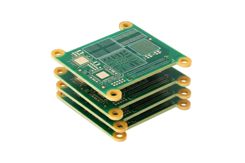
A water treatment PCB connects process sensors, pump/valve outputs, control logic, communications and power protection inside water, wastewater, dosing, filtration or monitoring equipment. Reliability depends on the actual enclosure, condensation, chemical vapors, surge environment and maintenance model—not on a “waterproof PCB” label.
Key takeaways
- Separate low-level pH/ORP/conductivity inputs from motor, relay, solenoid and switch-mode current paths.
- Define sensor cable length, shielding, isolation and field grounding before selecting the analog interface.
- Conformal coating reduces exposure only when the assembly is clean, compatible and correctly masked.
- Creepage and clearance follow voltage, pollution degree, altitude, material group and governing safety standard.
- Protect field wiring against ESD, EFT/burst, surge, miswiring and ground-potential differences.
- Validate the final enclosure, connectors, vents and cable glands; the bare PCB does not carry an IP rating.
Map the water-treatment control interfaces
| Interface | Common design concerns | Useful production/system test |
|---|---|---|
| pH/ORP electrode | Very high source impedance, leakage, shielding and temperature compensation | Input leakage, injected voltage, calibration path |
| Conductivity | Excitation accuracy, polarization, range switching and cable capacitance | Reference load/cell simulator and range test |
| Turbidity/optical sensor | LED drive, photodetector noise, fouling and ambient light | Optical fixture or sensor simulator |
| 4-20 mA | Loop power, burden voltage, isolation, reverse wiring and surge | Programmable loop source across range/fault states |
| RS-485/Modbus | Termination, bias, common-mode range, isolation and surge | Network traffic, polarity, open/short and ground-offset tests |
| Pump/valve/relay | Inrush, inductive energy, contact life, thermal rise and fault containment | Load fixture, temperature and switching endurance |
Partition noisy power from sensitive measurement
The layout should follow current paths and field boundaries.
- Place sensor connectors, protection and first analog stage together.
- Keep pump, relay, solenoid and DC/DC switching loops compact and remote from sensor inputs.
- Route cable shields and protective earth according to the enclosure/system grounding plan.
- Use galvanic isolation where required by ground potential, safety or EMC—not as a substitute for poor routing.
- Keep ADC references, excitation sources and low-noise rails away from thermal and switching gradients.
- Provide service-safe test points without exposing high-impedance nodes to contamination.
Moisture, chemicals and corrosion
Start with an exposure profile: continuous humidity or condensation, salt aerosol, chlorine/ozone or hydrogen-sulfide vapor, cleaning agents, splashes, immersion risk, temperature cycling and expected service access.
| Protection option | Good fit | Limitation |
|---|---|---|
| Sealed/vented enclosure | Primary barrier for most controllers | Cable glands, pressure cycling and condensation still need validation |
| Conformal coating | Humidity, condensation and selected chemical exposure | Coverage, adhesion, rework, compatibility and masking are process-dependent |
| Selective potting | Connector exits or high-risk zones | Traps heat and complicates inspection/rework |
| Full encapsulation | Non-serviceable immersed or exposed module | Thermal stress, cure chemistry and irreparability |
Surface finish should be selected for assembly, storage and exposure. ENIG is not a universal corrosion solution, and no finish protects unsealed component leads, connectors or residues after assembly.
Coating and cleanliness controls
- Approve coating chemistry against component, label, connector, sensor and enclosure materials.
- Define no-coat areas, keepouts and required edge/lead coverage.
- Clean and dry using a validated process before coating.
- Inspect coverage using the coating's approved method, such as UV tracer where provided.
- Verify cure, adhesion and thickness per the released process.
- Test insulation resistance and functionality after conditioning.
Do not coat over uncured flux, moisture or unknown contamination. Ionic cleanliness limits and test methods should be agreed for the product/process rather than copied from a generic threshold.
Surge, safety and EMC plan
Water systems often connect long outdoor cables and inductive loads. Define the threat at each port.
- Coordinate fuses, current limiting, TVS/MOV/GDT devices and isolation barriers.
- Check protective-device leakage and capacitance on sensor inputs.
- Provide flyback or snubber networks matched to the actual valve/relay/contactor load.
- Size traces, terminals and connectors from current, temperature rise and fault clearing.
- Derive spacing from IEC 60664-1 or the applicable product standard.
- Test EFT/burst, surge, ESD, conducted/radiated immunity and emissions on the assembled equipment.
Failure-mode matrix
| Symptom | Likely contributors | Investigation |
|---|---|---|
| pH/ORP drift in humidity | Surface leakage, residue, connector/cable ingress | Clean/dry comparison, insulation test, humidity conditioning |
| Random resets when a pump starts | Supply dip, inductive transient, ground bounce or radiated coupling | Rail capture, current path, EFT/surge test |
| Corrosion under coating | Contamination, incomplete cure, pinholes or incompatible chemistry | Microscopy, coating removal, process/cleanliness records |
| RS-485 failures between buildings | Ground offset, surge, termination or shield error | Differential/common-mode capture and isolation review |
| Hot terminal or relay area | Undersized path, loose connector, contact loss or overload | Thermal image, torque/contact and current test |
| Condensation after temperature change | Enclosure breathing, thermal mass or vent/drain design | Temperature/humidity cycle with final enclosure |
Water treatment PCB RFQ checklist
- Process type, installation location and service life target
- Sensor models, signal ranges, cable lengths and calibration interfaces
- Pump/valve/relay loads, inrush, switching rate and fault protection
- Supply, grounding, isolation and field-port surge/EMC requirements
- Temperature, humidity, condensation, salt/chemical and cleaning exposure
- Enclosure/IP target, venting, glands, connectors and potting/coating scope
- PCB, BOM, placement, firmware/configuration and approved substitutions
- Functional fixture, environmental conditioning and compliance tests
- Quantities, first article, traceability and change notification
Use turnkey PCB assembly and submit the controlled package through the PCB quotation page.
Standards and scope
- IEC 61010-1 — Safety requirements for measurement, control and laboratory equipment
- IEC 60664-1 — Insulation coordination
- IEC 61326-1 — EMC requirements for measurement, control and laboratory equipment
- IEC 60068-2-78 — Damp heat, steady state
- IEC 60529 — Degrees of protection provided by enclosures
- IPC-CC-830 — Qualification and performance of electrical insulating compounds for printed wiring assemblies
Confirm current revisions and the equipment-specific regulatory route. PCB fabrication or coating does not independently establish an enclosure IP rating or certify the complete water-treatment system.
Water treatment PCB FAQ
Is a conformal-coated PCB waterproof?
No. Coating reduces selected environmental exposure but does not make connectors, components, enclosure penetrations or the complete assembly waterproof.
Is ENIG always the best finish for water-treatment electronics?
No. Finish selection depends on assembly, storage, component pitch and exposure. Environmental protection is primarily a system, cleanliness, coating and enclosure decision.
Should every water-treatment board use high-Tg FR-4?
Not automatically. Select laminate from assembly temperature, operating temperature, plated-hole reliability, moisture, mechanical and electrical requirements.
What is the most common cause of sensor drift in humidity?
Surface leakage from moisture and contamination is a common cause, but cable ingress, connector leakage, reference drift and sensor aging must also be checked.
Can the PCB receive an IP67 or IP68 rating?
IP ratings apply to enclosures under specified tests. The final housing, seals, vents, connectors and assembly must be evaluated together.