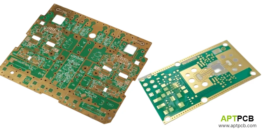
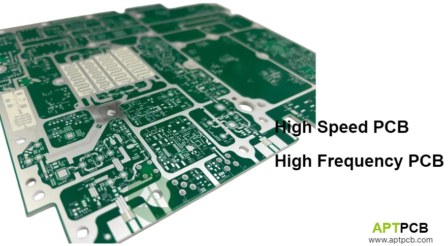
High speed and high frequency PCB applications share overlapping challenges but address fundamentally different circuit types with distinct design priorities and manufacturing requirements. High-speed designs handle digital signals with fast edge rates—DDR memory interfaces, PCIe links, USB connections—where signal integrity during transitions determines performance. High-frequency designs handle analog RF signals—wireless transceivers, radar front-ends, satellite links—where continuous wave behavior and impedance matching govern performance.
Understanding these distinctions enables appropriate material selection, tolerance specifications, and manufacturing processes for each application type.
Distinguishing High Speed from High Frequency
The terms "high speed" and "high frequency" are sometimes used interchangeably but describe different aspects of circuit behavior requiring different approaches.
High-Speed Digital Characteristics
High-speed design focuses on digital signals characterized by fast edge rates regardless of clock frequency:
- A 100 MHz clock with 500 ps rise time contains harmonic content extending to several GHz
- The fast transitions—not the clock frequency—determine when transmission line effects matter
- Critical parameter: edge preservation for reliable data capture
- Measured by: eye diagram quality, timing margin, jitter
Example: PCIe Gen 4 operates at 8 GT/s (4 GHz effective) with rise times under 35 ps, requiring careful transmission line design despite being a "digital" interface.
High-Frequency Analog Characteristics
High-frequency design addresses analog RF signals at elevated carrier frequencies:
- Typically 500 MHz to 100+ GHz carrier frequency
- Characterized by continuous wave behavior, not edges
- Critical parameter: impedance matching for power transfer
- Measured by: S-parameters, insertion loss, return loss, phase accuracy
Example: A 2.4 GHz WiFi front-end requires precise 50Ω impedance throughout the signal path to maximize transmitted power and received sensitivity.
Why the Distinction Matters
Manufacturing priorities differ between applications:
| Aspect | High-Speed Digital | High-Frequency Analog |
|---|---|---|
| Primary loss concern | Eye closure budget | Link budget/sensitivity |
| Critical tolerance | Timing/length matching | Impedance accuracy |
| Acceptable Df | 0.01-0.02 often OK | 0.002-0.004 required |
| Via concern | Stub resonance | Impedance discontinuity |
| Key measurement | TDR, eye diagram | VNA S-parameters |
Comparing Material Selection Requirements
Material selection criteria differ between applications, with each domain prioritizing different properties.
High-Speed Digital Materials
High-speed digital prioritizes:
Dk Uniformity: Consistent dielectric constant across board area ensures uniform impedance for all signal traces. A ±5% Dk variation creates ±2.5% impedance variation—acceptable for most digital interfaces with built-in equalization.
Moderate Loss Acceptable: Loss primarily affects eye diagram opening rather than absolute power transfer. DDR4 channels can tolerate 8-10 dB insertion loss with proper equalization.
Cost Sensitivity: High-volume digital products often use enhanced FR-4 variants (Dk variation <±3%, Df 0.008-0.015) balancing performance with economics.
High-Frequency Analog Materials
High-frequency analog demands:
Lowest Dissipation Factor: Df directly impacts insertion loss accumulating along RF paths. Requirements typically:
- Below 10 GHz: Df < 0.004 (hydrocarbon ceramics)
- 10-40 GHz: Df < 0.002 (PTFE-based)
- Above 40 GHz: Df < 0.001 (ultra-low-loss PTFE)
Tight Dk Tolerance: Filter center frequencies and matching network impedances depend on Dk accuracy—typically ±2% required.
Premium Materials Justified: Performance requirements often justify PTFE-based materials despite higher cost.
Hybrid Designs
Systems combining digital processing with RF front-ends—software-defined radios, 5G systems, radar processors—require multilayer constructions mixing material types. Premium RF materials serve antenna and transceiver sections; cost-effective materials support digital processing.
Key Material Selection Factors
- High-Speed Dk Requirements: Consistent Dk across board area (±3-5% acceptable).
- High-Frequency Df Requirements: Lowest possible Df for operating frequency.
- High-Speed Loss Tolerance: Moderate Df acceptable within timing budget.
- High-Frequency Dk Precision: Tight tolerance (±2%) for designed responses.
- Cost-Performance Balance: Enhanced FR-4 for high-speed; PTFE for high-frequency.
- Hybrid Approaches: Mixed materials optimizing both domains.
Analyzing Signal Integrity Requirements
Both domains require controlled impedance, but specific structures, tolerances, and verification approaches differ.
High-Speed Digital Impedance
High-speed extensively uses differential signaling:
Differential Pair Requirements:
- Matched impedance between positive and negative traces (typically 85-100Ω differential)
- Length matching within 5-10 mils for timing
- Controlled coupling (loose coupling preferred for routing flexibility)
- Common-mode rejection from balanced structure
Impedance Tolerance: ±10% often acceptable—modern interfaces include equalization compensating for moderate variations.
Via Management: Focus on stub resonance elimination through back-drilling or blind vias, particularly for high-speed serial links.
High-Frequency Analog Impedance
High-frequency requires consistent single-ended impedance:
Transmission Line Requirements:
- 50Ω throughout signal path including matching networks
- Tolerance typically ±5% or tighter for demanding RF
- Phase accuracy may require ±1° (±0.3% length accuracy)
Matching Network Implementation: Quarter-wave transformers and distributed elements require both impedance and length accuracy.
Isolation Emphasis: Section-to-section isolation (transmit/receive) often >60 dB, requiring via fencing and shielding.
Key Signal Integrity Considerations
- Differential Pairs: High-speed requires matched pairs through HDI techniques for dense routing.
- Single-Ended RF: High-frequency requires consistent 50Ω throughout.
- Tolerance Requirements: High-speed ±10%; high-frequency ±5% or tighter.
- Via Focus: High-speed addresses stubs; high-frequency addresses discontinuity.
- Isolation: High-frequency emphasizes section shielding; high-speed emphasizes crosstalk.
- Phase Accuracy: High-frequency applications may require precise phase matching.
Addressing Thermal and Power Considerations
Thermal management requirements differ based on heat sources and temperature sensitivity.
High-Speed Digital Thermal
Heat sources in high-speed digital:
- Processors, FPGAs, memory controllers—concentrated, high power density
- Voltage regulators—localized but predictable
- I/O drivers—distributed but lower power
Management approaches:
- Thermal via arrays beneath major ICs
- Heavy copper power planes for heat spreading and current capacity
- Heatsink attachment provisions
- Power distribution network (PDN) managing di/dt transients
High-Frequency Analog Thermal
Heat sources in high-frequency analog:
- Power amplifiers—may dissipate 50-60% of input power as heat
- Oscillators—temperature-sensitive requiring thermal stability
- Distributed throughout RF chain
Management complexity:
- Temperature affects gain, noise figure, and frequency stability more directly than digital
- Thermal design critical for consistent RF performance
- May require thermal isolation from digital sections in hybrid designs
Key Thermal Management Approaches
- Digital Focus: Thermal vias and heavy copper beneath concentrated IC heat sources.
- RF Focus: PA thermal management with attention to temperature effects on RF parameters.
- Power Distribution: PDN design for digital; filtered bias for RF.
- Thermal Isolation: Preventing digital heat from affecting temperature-sensitive RF in hybrid designs.
Implementing Testing and Verification
Testing reflects different performance metrics between domains.
High-Speed Digital Testing
TDR Impedance: Verifies controlled impedance for single-ended and differential traces.
Channel Characterization:
- Insertion loss (S21) across frequency
- Crosstalk (NEXT, FEXT) between adjacent channels
- Return loss (S11) indicating impedance matching
Eye Diagram: System-level validation showing timing margin and noise performance.
High-Frequency Analog Testing
Vector Network Analysis:
- S-parameters (S11, S21, S12, S22) across operating bandwidth
- Return loss indicating impedance match quality
- Insertion loss quantifying signal attenuation
- Isolation between ports
Phase Measurement: Electrical length accuracy for distributed circuits.
Functional Testing: Power output, noise figure, frequency accuracy for active circuits.
Key Testing Approaches
- High-Speed TDR: Impedance profiling for transmission lines.
- High-Frequency VNA: S-parameter characterization across bandwidth.
- Channel Loss: Insertion loss supporting data rate requirements.
- Phase Accuracy: Electrical length verification for RF distributed circuits.
- Dimensional Verification: Trace geometry confirming manufacturing tolerances.
- Process Capability: Statistical monitoring through comprehensive quality systems.
Supporting Diverse Application Requirements
Both markets span diverse products with varied requirements.
High-Speed Applications
- Consumer electronics with moderate requirements
- Data center infrastructure demanding highest performance
- Memory interfaces (DDR4/DDR5) with specific impedance specifications
- High-speed serial links (PCIe, USB, Ethernet) requiring channel optimization
High-Frequency Applications
- IoT wireless modules—cost-sensitive, moderate performance
- Telecommunications infrastructure—5G base stations, backhaul
- Automotive radar—77 GHz with automotive quality requirements
- Aerospace/defense—demanding performance across extreme environments
Understanding whether applications are fundamentally high-speed digital or high-frequency analog—or hybrid combinations—guides appropriate specification and manufacturing approaches.
For comprehensive manufacturing information, see our guide on high frequency PCB manufacturing.