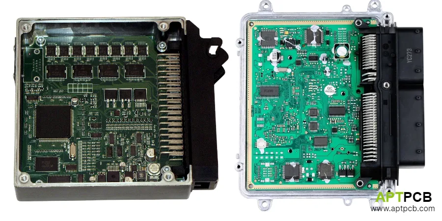
Engine Control Units represent the most demanding automotive PCB application—continuous operation at temperatures from -40°C to +150°C, exposure to fuel vapors and oil contamination, extreme vibration, and electromagnetic environments that include ignition noise, alternator ripple, and load dump transients. The ECU PCB must maintain precision control of fuel injection, ignition timing, and emissions systems while surviving 15+ years of harsh engine compartment conditions.
This guide examines ECU PCB design requirements: material selection for extreme temperatures, EMC design for automotive compliance, sensor interface implementation, power stage integration for direct injector and ignition drive, thermal management within sealed enclosures, and manufacturing standards for automotive qualification.
In This Guide
- Material Selection for Extreme Automotive Temperatures
- EMC Design for Automotive Compliance
- Sensor Interface Implementation
- Power Stage Integration for Injectors and Ignition
- Thermal Management in Sealed Enclosures
- Automotive Manufacturing and Qualification
Material Selection for Extreme Automotive Temperatures
Engine compartment ECUs operate continuously at ambient temperatures reaching 125°C, with localized hot spots from power components potentially exceeding 150°C. Standard FR-4 materials (Tg 130-140°C) cannot reliably survive these conditions—the glass transition temperature must exceed maximum operating temperature with margin to prevent laminate degradation.
Beyond Tg considerations, thermal cycling from -40°C to +150°C creates mechanical stress from CTE mismatch between materials. Repeated thermal excursions fatigue solder joints and via structures; material selection and construction techniques must accommodate this stress.
High-Temperature Material Requirements
- Glass Transition Temperature: Minimum Tg 170°C recommended; Tg 180°C+ for highest-temperature applications—measured by DSC or TMA method matters.
- Decomposition Temperature: Td (5% weight loss) should exceed 340°C; ensures laminate stability during assembly and operation.
- CTE Matching: Z-axis CTE below 50 ppm/°C through Tg; excessive CTE stresses via barrels during thermal cycling.
- CAF Resistance: High-Tg materials typically offer improved CAF resistance; verify specifications for automotive humidity exposure.
- Material Examples: Isola 370HR, Panasonic R-1566/R-1755, or equivalent high-Tg, low-CTE materials designed for automotive.
- Copper Adhesion: Verify copper peel strength maintained at elevated temperature; degradation indicates potential reliability issues.
Material selection affects both manufacturing processability and long-term reliability—consult high-Tg PCB specifications for automotive-grade options.
EMC Design for Automotive Compliance
Automotive EMC requirements (CISPR 25 for emissions, ISO 11452 for immunity) exceed typical commercial specifications—vehicles incorporate sensitive receivers, critical safety systems, and operate near high-power transmitters. ECU designs must survive load dump transients (up to +100V), reverse polarity, and conducted disturbances while controlling emissions that could interfere with other vehicle systems.
The harsh electromagnetic environment within the engine compartment—ignition system noise, alternator harmonics, starter motor transients—requires robust immunity design beyond standard EMC practices.
EMC Design Strategies
- Power Entry Filtering: LC filters at power input attenuate conducted emissions and provide transient protection; TVS diodes clamp load dump spikes.
- Ground Plane Design: Solid ground planes minimize inductance and provide shielding; avoid splits that create antenna structures.
- Signal Filtering: Ferrite beads and RC filters on all signals entering/exiting enclosure; filter bandwidth appropriate for signal requirements.
- Shield Can Integration: Critical circuits may require additional shield cans; design mounting provisions and ground connections.
- Connector Filtering: Filtered connectors or PCB filter networks at connector interface; last line of defense before signals exit enclosure.
- Return Path Control: Ensure well-defined return paths for all signals; floating returns create common-mode issues and EMI problems.
EMC compliance requires integrated design approach—retrofitting EMC solutions rarely succeeds and adds cost versus designed-in protection.
Sensor Interface Implementation
ECUs interface with numerous sensors: crankshaft/camshaft position, mass airflow, manifold pressure, throttle position, coolant temperature, oxygen sensors, and knock sensors. Each sensor type has specific interface requirements—from simple resistive temperature sensors to complex wideband oxygen sensor heating and measurement circuits.
Sensor inputs must survive harsh conditions including ESD events, miswiring, and exposure to vehicle electrical transients while maintaining measurement accuracy required for precise engine control.
Sensor Circuit Design
- Input Protection: TVS diodes and series resistors protect against ESD and overvoltage; protection must not affect measurement accuracy.
- Signal Conditioning: Operational amplifier circuits provide gain, filtering, and level shifting; rail-to-rail op-amps maximize dynamic range.
- ADC Requirements: 10-12 bit ADC resolution typical; sample rate matched to sensor dynamics—crankshaft position requires higher rates than temperature.
- Reference Voltage: Precision references for sensor excitation and ADC reference; temperature stability critical for accuracy.
- Isolation Requirements: Some sensors may require galvanic isolation; high-side current sensing particularly challenging.
- Wiring Fault Protection: Circuits must survive short-to-battery, short-to-ground, and open-circuit conditions without damage.
Sensor interface quality directly affects engine control precision—poor signal conditioning degrades combustion efficiency and emissions performance.
Power Stage Integration for Injectors and Ignition
ECUs directly drive fuel injectors and ignition coils—high-current switching circuits that generate substantial heat and electrical noise. Modern direct-injection systems operate at hundreds of volts and require precise current control; ignition systems switch primary currents exceeding 10A with microsecond timing accuracy.
Integrating these power stages on the ECU main board requires careful layout to prevent noise coupling while managing thermal loads. Some designs separate power stages onto daughter boards, but integration trends favor single-board solutions for cost and reliability.
Power Stage Design
- Injector Drivers: High-side or low-side switching depending on architecture; current sensing for diagnostic feedback; peak-and-hold current profiles for fast opening.
- Ignition Drivers: High-current switching with inductive load protection; dwell time control for coil charging; flyback energy management.
- Thermal Management: Power MOSFETs require thermal path to board and enclosure; thermal vias and copper pour provide heat spreading.
- Noise Isolation: Physical separation between power stage and sensitive analog circuits; ground plane partitioning prevents noise coupling.
- Protection Circuits: Over-temperature, over-current, and short-circuit protection; diagnostic capability for fault detection and reporting.
- Gate Drive Design: Proper gate drive ensures efficient switching; inadequate drive increases switching losses and EMI.
Power stage implementation requires understanding both power electronics and heavy copper PCB design for adequate current handling.
Thermal Management in Sealed Enclosures
ECU enclosures seal against moisture and contaminant ingress—typically IP67 or better rating—eliminating airflow as a cooling mechanism. All heat generated by power stages and processing must conduct through the PCB to the enclosure, then dissipate to ambient through the enclosure surface.
The thermal design challenge intensifies for modern ECUs incorporating more processing power for advanced engine control algorithms while fitting existing mounting locations with established thermal budgets.
Thermal Design Approaches
- Thermal Via Arrays: Dense arrays beneath power components conduct heat to internal layers and potting material; filled vias maximize thermal conductivity.
- Metal Core Options: Aluminum or copper substrates provide superior heat spreading for high-power designs; increased cost and manufacturing complexity.
- Enclosure Contact: Direct thermal interface between PCB and metal enclosure; requires flat mounting surfaces and appropriate TIM.
- Component Selection: Select ICs with exposed thermal pads; low-RDS(on) MOSFETs reduce conduction losses; efficient power supply designs minimize heat generation.
- Thermal Simulation: FEA thermal analysis validates design before prototyping; identifies hot spots requiring design revision.
- Potting Considerations: Many ECUs use potting compound for additional thermal path; potting thermal conductivity affects system performance.
Thermal management directly affects reliability—elevated temperatures accelerate component aging and reduce service life.
Automotive Manufacturing and Qualification
Automotive ECU manufacturing requires IATF 16949 quality management systems, AEC-Q component qualification, and extensive validation testing. The combination of high-reliability requirements, long product lifecycles (15+ years), and production volumes drives manufacturing approaches emphasizing process control and traceability.
Qualification testing validates designs against environmental, mechanical, and electrical stress conditions representing worst-case field exposure. Failed qualification requires design revision and retest—early design reviews against requirements prevent late-stage issues.
Manufacturing and Qualification Requirements
- IATF 16949: Quality management system certification required for automotive suppliers; documented processes, calibration, and traceability.
- AEC-Q Components: Components qualified to AEC-Q100 (ICs), AEC-Q101 (discretes), AEC-Q200 (passives) standards; verified temperature range and reliability.
- PPAP Documentation: Production Part Approval Process documentation demonstrates manufacturing capability; required before production release.
- Environmental Testing: Temperature cycling (-40°C to +150°C), thermal shock, humidity, vibration, and mechanical shock per OEM specifications.
- EMC Validation: Complete vehicle-level EMC testing per manufacturer requirements; typically ISO/CISPR standards with OEM-specific additions.
- Reliability Targets: Automotive reliability targets typically <10 ppm defect rate; requires robust design and manufacturing controls.
Automotive programs require manufacturing partners with demonstrated automotive quality systems and production experience.
Technical Summary
ECU PCB design exemplifies automotive electronics challenges—extreme temperatures, harsh EMC environment, power stage integration, and reliability requirements exceeding most other applications. Success requires integrated approach addressing materials, EMC, thermal, and manufacturing considerations from initial design phases.
Key decisions include material selection (temperature capability and long-term stability), power stage architecture (integration level and thermal strategy), EMC protection approach (filtering and shielding strategy), and manufacturing qualification path (test plan and documentation requirements).
Design reviews against automotive requirements early in development prevent costly late-stage discoveries; engage automotive-qualified manufacturing partners during design to ensure manufacturing feasibility.