LED video displays transform spaces through dynamic visual communication—from retail signage capturing attention to stadium screens delivering immersive experiences. Behind every pixel lies sophisticated PCB design managing thousands of LEDs with precise timing, consistent brightness, and reliable operation across challenging environmental conditions.
LED display PCB design differs fundamentally from general LED lighting. Where lighting applications prioritize efficiency and thermal management, displays demand pixel-level control at video refresh rates, uniform appearance across vast arrays, and serviceability enabling field module replacement. These requirements create unique design challenges spanning high-speed signal distribution, driver integration, and modular architecture.
This guide addresses LED display PCB engineering from pixel driver architecture through production-ready design, serving engineers developing indoor, outdoor, and specialty display systems.
Understanding LED Display Architecture
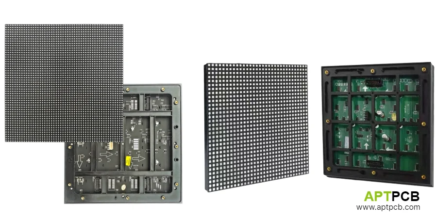
LED display systems organize into hierarchical levels: individual LEDs form pixels, pixels arrange into modules, modules assemble into cabinets, and cabinets combine to create complete displays. Each level presents distinct PCB design considerations—from pixel-level driver integration to module-level signal distribution and power management.
Pixel pitch—the center-to-center distance between adjacent pixels—largely determines display resolution and viewing characteristics. Fine-pitch displays (under 2mm) suit close viewing distances; coarse-pitch displays (10mm+) serve outdoor applications viewed from greater distances. Pitch selection cascades through the entire design: finer pitch requires more LEDs per area, more driver channels, higher PCB density, and greater thermal management attention.
Display Architecture Fundamentals
- Pixel Configuration: RGB pixels contain separate red, green, and blue LEDs (or dies within single package). Pixel pitch determines LED density—1.5mm pitch means approximately 444,000 pixels per square meter requiring 1.33 million individual LED control points for RGB.
- Module Organization: Modules typically range from 160mm × 160mm to 320mm × 320mm, containing complete driver and power electronics. Module granularity enables field service through module replacement rather than component-level repair.
- Refresh Rate Requirements: Video applications require minimum 60Hz refresh, while broadcast and camera-facing installations demand 240Hz or higher to eliminate banding artifacts in recorded content. Refresh rate directly affects driver IC timing requirements.
- Grayscale Resolution: 10-14 bit grayscale provides smooth transitions without visible banding. Higher bit depth requires faster data rates and more sophisticated driver ICs. High-speed signal integrity becomes increasingly important.
- Brightness Specifications: Outdoor displays require 5,000-10,000 nits for sunlight visibility; indoor displays typically 600-1,500 nits. Higher brightness increases power density and thermal challenge proportionally.
- Uniformity Standards: Module-to-module and pixel-to-pixel brightness variation must remain below visible thresholds—typically ±5% brightness and ±0.003 Δu'v' color.
Implementing Pixel Driver Architecture
Driver architecture determines how pixel data translates to LED current. Constant-current driver ICs receive serial data specifying brightness for each channel, convert to PWM duty cycle, and sink corresponding current through connected LEDs. Driver selection and implementation critically affect image quality, refresh capability, and power efficiency.
Modern LED display drivers integrate significant functionality—shift registers, data latches, PWM generators, and constant-current sinks in single packages. These ICs typically provide 16, 24, or 48 channels, with emerging devices offering 96+ channels to reduce component count for fine-pitch displays.
Driver Implementation Considerations
- Channel Count Optimization: Balance IC channel count against routing density. Higher channel count reduces IC quantity but concentrates routing at IC locations. Distribute drivers across module area for manageable routing.
- Current Accuracy: Channel-to-channel current matching affects brightness uniformity. Premium drivers achieve ±3% matching; standard devices ±5-6%. Specify based on uniformity requirements.
- PWM Frequency: Higher PWM frequency reduces flicker visibility and improves camera compatibility. Modern drivers support 1kHz+ internal PWM; premium devices reach 10kHz+ for broadcast applications.
- Data Interface Design: Serial data, clock, and latch signals must maintain integrity across module area. Terminate lines appropriately; consider differential signaling for critical paths.
- Thermal Impact: Driver ICs dissipate power proportional to output current and internal drop. At high brightness, driver heating can exceed LED heating. Plan thermal paths for driver areas.
- Fault Management: Some drivers include open/short LED detection supporting diagnostic and error mapping. Consider fault detection requirements for maintenance efficiency.
Designing Signal Distribution Networks
Signal distribution across LED display modules presents high-speed design challenges. Clock signals distributing to all drivers must maintain edge quality and timing alignment. Data signals must reach destinations without corruption despite PCB trace lengths and environmental interference.
Signal Routing Strategies
- Clock Distribution: Central clock sources with controlled trace lengths to all drivers maintain timing coherence. Buffer clock at distribution points if fan-out or distance challenges signal quality.
- Data Path Topology: Daisy-chain data through driver ICs reduces routing density but accumulates propagation delay. Parallel distribution enables faster refresh but increases routing complexity.
- Impedance Control: Control trace impedance (typically 50Ω single-ended, 100Ω differential) through controlled stackup design. Maintain consistency along signal paths.
- EMC Considerations: High-speed clocks and data generate emissions requiring attention for regulatory compliance. Return path integrity, signal rise time control, and appropriate termination reduce emissions.
- Inter-Module Connection: Module-to-module signals require robust connectors with appropriate contact count, current capacity, and mating cycles. Plan connector placement for assembly efficiency and service access.
- Redundancy Options: Critical installations may require signal redundancy preventing single-point failures. Design architecture supporting backup signal paths where reliability requirements dictate.
Addressing Display-Specific Thermal Design
LED display thermal design differs from general lighting: moderate power density distributed across many small sources rather than concentrated high power. The challenge lies in maintaining uniform temperature across large arrays while accommodating variable content creating localized heating patterns.
Thermal Design Approaches
- Distributed Heat Sources: Many LEDs at moderate current create distributed thermal load. Uniform copper distribution and adequate substrate thermal conductivity maintain temperature uniformity.
- Content-Dependent Loading: Static content (logos, tickers) creates sustained localized heating while surrounding dark areas remain cool. Design for continuous operation of partial area at maximum brightness.
- Substrate Selection: Standard FR-4 often adequate for indoor displays at typical brightness. Higher brightness or outdoor applications may require metal-core or enhanced thermal substrates.
- Cabinet Ventilation: Natural convection or forced air through module cabinets removes heat from LED modules. Design mounting provisions maintaining thermal contact while enabling airflow.
- Driver Thermal Management: Driver IC power dissipation may rival LED dissipation at high refresh rates. Provide thermal relief paths from driver locations.
- Environmental Operation: Outdoor displays face solar loading adding to LED heat generation. Account for worst-case combination of maximum ambient, solar loading, and maximum brightness content.
Implementing Modular Design for Serviceability
Field serviceability requirements fundamentally shape LED display PCB design. Module-level replacement enables display maintenance without specialized electronics skills—critical for commercial installations where downtime costs money.
Module boundaries must accommodate complete functional units with well-defined interfaces. Module-to-module variation must remain below visible thresholds. Mechanical features must enable rapid, reliable module exchange.
Modular Design Requirements
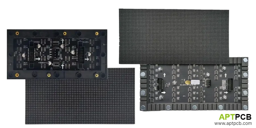
- Functional Completeness: Each module contains LEDs, drivers, and power conversion necessary for independent pixel control. Input interface accepts system power and data; no adjustment required during installation.
- Interface Standardization: Define electrical interfaces (connectors, signal levels) and mechanical interfaces (mounting, alignment) enabling module interchangeability across production lots and replacement inventory.
- Calibration Data: Module-level calibration data stored in local EEPROM enables matching without system-level adjustment. Include calibration interface provisions in module design.
- Visual Alignment: Module edges must align precisely for uniform appearance. Design appropriate board profile tolerances and alignment features enabling pixel-level registration.
- Handling Features: Include provisions for module extraction tools and handling during replacement. Avoid damage-prone connectors or fragile features at handling zones.
- Quality Traceability: Serial number identification enabling production lot tracking and failure analysis. Supports warranty administration and quality improvement.
Meeting Environmental and Reliability Requirements
LED displays operate in environments from climate-controlled interiors to direct outdoor exposure—each presenting distinct reliability challenges. Design and material selection must address intended operating environment while achieving reliability expectations appropriate to application value.
Environmental Design Factors
- IP Rating Achievement: Outdoor displays require water and dust protection. Module potting or conformal coating protects circuits; front-face sealing prevents moisture intrusion at LED mounting.
- Temperature Range: Outdoor displays face -40°C to +70°C extremes. Component selection, material CTE matching, and high-Tg substrates ensure survival across temperature range.
- UV Stability: Direct sunlight exposure degrades some materials. Select LED packages, encapsulants, and solder mask formulations with demonstrated UV stability.
- Humidity Resistance: High humidity with temperature cycling creates condensation risk. Conformal coating or hermetic sealing protects moisture-sensitive circuits.
- Vibration and Shock: Transportation and installation impose mechanical stress. Design mounting provisions and connector selection for mechanical robustness. Assembly quality testing validates mechanical reliability.
- Lifetime Expectations: Commercial displays expected 50,000-100,000 hour operation. LED selection, thermal design, and component quality must support lifetime objectives.
Summary
LED display PCB design integrates pixel driver architecture, high-speed signal distribution, thermal management, modular serviceability, and environmental reliability into manufacturable products. The combination of high LED count, precise timing requirements, and demanding operating environments creates design challenges distinct from other LED applications.
Success requires understanding display system architecture and how module-level PCB design supports overall system requirements. Driver selection and implementation determine image quality; signal distribution maintains timing integrity; thermal design ensures uniform appearance; modular architecture enables field service; environmental protection provides application longevity.
The investment in proper display PCB engineering enables products achieving visual quality, reliability, and serviceability that commercial display applications demand.