LED modules provide pre-engineered LED assemblies that luminaire manufacturers integrate into lighting products without developing LED PCBs from scratch. This modular approach accelerates product development, reduces design risk, and enables smaller manufacturers to offer competitive lighting products by leveraging module suppliers' LED expertise.
Module PCB design balances standardization enabling broad application against optimization for specific use cases. Successful modules meet diverse luminaire requirements while maintaining consistent quality and performance specifications that integrators depend upon. Understanding module architecture, interface standards, and integration requirements enables both effective module development and informed module selection.
This guide addresses LED module PCB design from both module developer and luminaire integrator perspectives.
Understanding LED Module Architecture
LED modules encapsulate the complexity of LED circuit design into characterized assemblies with defined interfaces. Module architecture determines applicability across luminaire types, integration requirements for adopters, and manufacturing efficiency for module producers.
Module boundaries significantly affect design decisions. Comprehensive modules including driver simplify luminaire design but constrain driver selection. LED-only modules provide flexibility but require luminaire-level driver integration. The appropriate scope depends on target applications and market expectations.
Module Architecture Options
- LED-Only Modules: Contain LEDs and immediate interconnection only. Integrator provides driver, thermal path, and mechanical mounting. Maximum flexibility at expense of integration complexity.
- Driver-Integrated Modules: Include on-board driver converting AC mains or DC input to LED current. Simplified integration—input power and controls only. Limited flexibility for driver-specific requirements.
- Modular Light Engines: Complete optical systems including LEDs, drivers, and primary optics (reflectors, lenses). Enable rapid luminaire development; constrain product differentiation through optical design.
- Zhaga Standardization: Industry consortiums define standard module footprints and interfaces enabling interchangeable modules across manufacturers. Design to standard form factors when broad compatibility matters.
- Application-Specific Modules: Optimized for particular luminaire types: linear for troffers, circular for downlights, rectangular for panels. Specialization enables performance optimization.
- Scalable Module Families: Related modules at different power levels sharing mounting interface and driver compatibility. Enables luminaire product families from common design effort.
Designing Electrical Interfaces
Electrical interface design determines module compatibility with drivers, controls, and safety systems. Clear interface specifications prevent integration problems; ambiguous specifications create field issues when modules encounter unexpected system configurations.
Electrical Interface Specifications
- Input Voltage Range: Constant-voltage modules specify acceptable DC input range matching common driver outputs (12V, 24V, 48V). Include tolerance band accounting for driver regulation accuracy and distribution losses.
- Constant-Current Interface: Modules designed for constant-current drivers specify current rating and compliance voltage range. Document LED string configuration enabling driver selection.
- Dimming Compatibility: Define supported dimming methods (PWM, analog, protocol-based) with interface requirements. Specify dimming range and smoothness achievable with module design.
- Connector Selection: Select connectors based on current capacity, wire gauge accommodation, mating cycles, and reliability requirements. Industrial-grade connectors suit demanding applications.
- Polarity Protection: Include reverse polarity protection appropriate to expected installation—LED-only modules may rely on driver protection; stand-alone modules should incorporate protection.
- Safety Certifications: Design supporting intended safety certifications (UL, CE, etc.). Maintain required clearance and creepage distances; document for certification submission.
Engineering Thermal Integration
Module thermal design must enable effective heat transfer to luminaire heatsinking rather than providing complete thermal solution. Modules connect to diverse heatsinks—some application-specific, others standardized—requiring thermal interface design supporting range of integration approaches.
Thermal Integration Approaches
- Thermal Interface Surface: Designate module surface(s) for heatsink contact. Ensure flatness specification enables good thermal interface; avoid components or features interrupting thermal contact area.
- Thermal Resistance Specification: Document module thermal resistance from LED junction to mounting surface (Rth j-mtg). This specification enables integrators to complete thermal calculations with their heatsink selection.
- Mounting Pressure Requirements: TIM performance depends on contact pressure. Specify required mounting force and acceptable methods. Include mounting hole provisions supporting appropriate force.
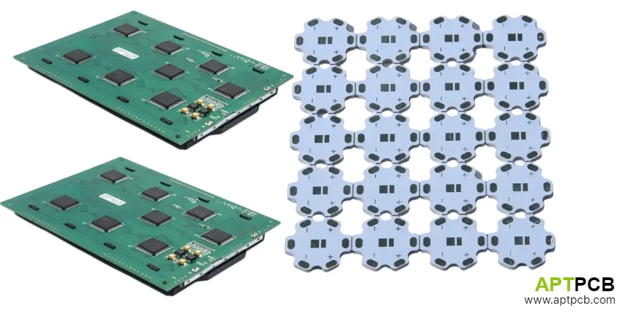
- Metal-core substrate selection: Most LED modules benefit from MCPCB providing excellent thermal path to mounting surface. Specify dielectric thermal conductivity based on power density and thermal budget allocation.
- Thermal Interface Material Guidance: Recommend compatible TIM types or provide TIM as module component. Document application method ensuring consistent performance.
- Test Conditions: Specify thermal test conditions (power level, mounting configuration, ambient temperature) enabling integrators to predict performance in their applications.
Implementing Optical Considerations
LED modules often include primary optic interface features—LED positioning for lens alignment, reflector mounting provisions, or secondary optic attachment points. These features must maintain positional accuracy across production variation.
Optical Interface Design
- LED Position Accuracy: Optical systems depend on LED positioning relative to optical elements. Specify position tolerance achievable through PCB fabrication and assembly processes; verify tolerance supports optical performance.
- Reference Features: Include reference features (edges, holes, fiducials) enabling optical component alignment. Position references relative to LEDs with appropriate tolerance.
- Mounting Provisions: Provide mounting features for reflectors, lenses, or other optical elements. Design for reliable attachment surviving thermal cycling and mechanical stress.
- Surface Reflectivity: PCB surface surrounding LEDs affects light extraction and uniformity. White solder mask improves optical efficiency for lighting products where board surface is optically active.
- Height Constraints: Document component heights affecting optical cavity dimensions. LED package height plus any connectors or components determines minimum optical clearance.
- LES Documentation: Provide light-emitting surface (LES) dimensional information enabling optical design integration. Include LED positions, active area dimensions, and optical characteristics.
Enabling Manufacturing Efficiency
Module PCB design significantly affects manufacturing cost and quality. Design decisions impacting fabrication, assembly, and test processes accumulate through production volumes—small per-unit impacts become significant at volume.
Manufacturing Design Considerations
- Panelization Efficiency: Design module outline for efficient panel utilization. Unusual shapes or aspect ratios may waste panel area increasing per-unit fabrication cost.
- Assembly Simplicity: Single-sided assembly simplifies process and reduces handling. When double-sided assembly necessary, minimize thermal-critical components on secondary side.
- Test Point Provisions: Include electrical test points enabling production testing and debugging. Define test requirements during design to ensure testability.
- Stencil Design: Thermal pad aperture patterns preventing void formation require specification in assembly documentation. Don't rely on assembler defaults for thermal-critical joints.
- Component Availability: Select components from multiple suppliers where possible. Single-source components create supply risk; specify approved alternatives for critical parts.
- Documentation Completeness: Provide complete fabrication and assembly specifications—substrate material, surface finish, solder mask type, assembly process requirements. Incomplete documentation invites interpretation that may not match design intent.
Supporting Application Diversity
Successful LED modules serve diverse applications—modules designed too narrowly limit market opportunity while modules attempting universal applicability may compromise performance for specific applications. Design decisions should consciously balance breadth against optimization.
Application Range Considerations
- Power Scalability: Consider module families at different power levels sharing thermal and mechanical interfaces. Enables luminaire product lines from common integration work.
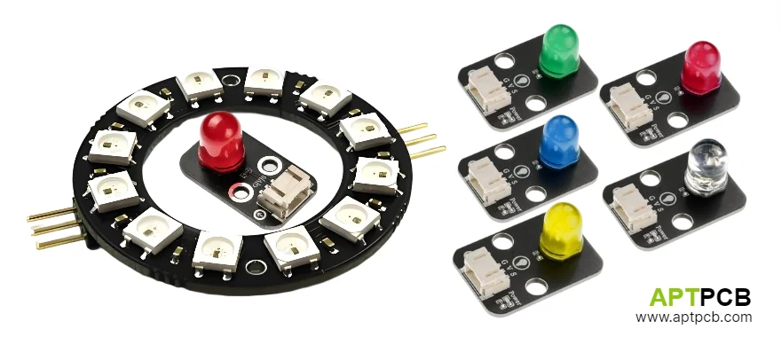
- Color Temperature Options: Offer CCT variants matching market demands. Consider tunable-white capability for premium applications; single CCT optimized for cost-sensitive applications.
- Driver Compatibility: Design electrical interface compatible with broad driver range. Document tested driver combinations to simplify integrator qualification.
- Application Characterization: Provide performance data for multiple operating conditions—power levels, temperatures, drive currents. Enable integrators to predict performance in specific applications.
- Mounting Flexibility: Consider multiple mounting orientations and configurations within single module design where application diversity benefits without compromising primary usage.
- Industry-specific considerations: Some applications (medical, automotive, industrial) impose specific requirements. Design modules for target industries with appropriate certifications and documentation.
Summary
LED module PCB design balances standardization enabling broad application against optimization for effective performance. Successful modules clearly define electrical interfaces, enable effective thermal integration, support optical system requirements, and achieve manufacturing efficiency at production volumes.
The module development investment pays dividends through reusable designs serving multiple luminaire products. Clear specifications and characterized performance enable integrators to successfully incorporate modules into their products with predictable results.
Whether developing LED modules for product offering or evaluating modules for integration, understanding module architecture and interface requirements enables informed decisions that lead to successful lighting products.