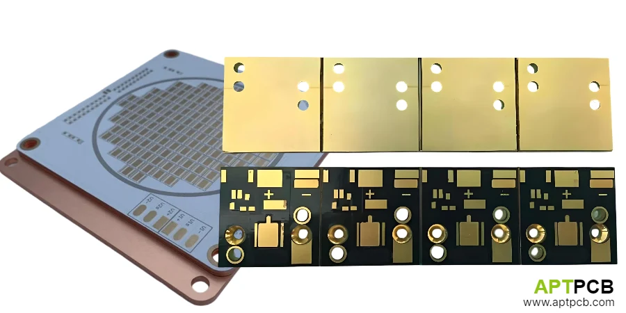
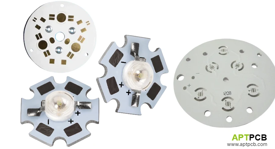
Metal core PCBs provide the thermal foundation for most commercial LED lighting products. The fundamental choice between aluminum and copper cores—and understanding when each material excels—enables thermal designs that achieve performance objectives at appropriate cost points.
Aluminum dominates LED MCPCB volume due to favorable cost-performance balance for typical applications. Copper's superior thermal conductivity (385 W/m·K versus aluminum's 150 W/m·K) provides advantages for specific conditions: concentrated heat sources, demanding thermal budgets, or applications where copper's other properties prove beneficial. Understanding the conditions favoring each material enables informed material selection.
Comparing Thermal Performance Characteristics
Thermal performance comparison extends beyond bulk conductivity numbers. Heat spreading effectiveness, dielectric integration, and system-level thermal behavior all affect practical performance in LED applications.
Both aluminum and copper MCPCBs use similar dielectric constructions—the polymer dielectric layer often represents the thermal bottleneck regardless of base metal. This reality means copper's conductivity advantage primarily benefits spreading resistance rather than through-substrate conduction.
Performance Analysis
- Bulk Conductivity: Copper conducts heat 2.5× faster than aluminum (385 vs 150 W/m·K). This advantage applies to lateral spreading; through-thickness performance depends primarily on dielectric.
- Spreading Resistance Impact: For concentrated heat sources (COB LEDs, small LED arrays), spreading resistance can dominate total thermal resistance. Copper's spreading advantage may reduce peak temperatures 10-20% compared to aluminum.
- Dielectric Bottleneck: Both aluminum and copper MCPCB use similar dielectric technologies. At 1.0 W/m·K dielectric, through-layer resistance of 1.0°C·cm²/W often dominates spreading resistance—reducing copper's advantage.
- Effective Performance Gain: Real-world improvement from copper cores varies from minimal (distributed heat sources, standard dielectric) to significant (concentrated sources, enhanced dielectric). Thermal simulation quantifies specific designs.
- System Integration: Heatsink interface and convection often dominate total thermal resistance. Copper core improvements may represent small fraction of total thermal path.
- Application-Specific Analysis: Evaluate copper benefit for specific application rather than assuming general superiority. Cost premium may not justify thermal improvement for many applications.
Evaluating Cost and Practical Considerations
Material cost, weight implications, and manufacturing factors affect copper versus aluminum selection beyond pure thermal comparison. Total cost of ownership includes these factors alongside thermal performance benefits.
Practical Factors
- Material Cost: Copper costs approximately 3× more than aluminum by weight, and copper is 3.3× denser—making copper core roughly 10× more expensive in raw material cost. Finished MCPCB typically 2.5-3.5× aluminum cost.
- Weight Implications: Copper MCPCB weighs approximately 3× more than equivalent aluminum construction. Weight matters for portable products, mounting structures, and shipping costs.
- Manufacturing considerations: Copper machines differently than aluminum. Verify fabricator capability with copper core before committing to design requiring copper MCPCB.
- Thermal Expansion Matching: Copper CTE (17 ppm/°C) closer to FR-4 than aluminum (23 ppm/°C). May benefit reliability in hybrid or multilayer constructions combining MCPCB with standard PCB.
- Corrosion Characteristics: Copper resists corrosion differently than aluminum. Consider environmental exposure and appropriate protective finishes for application environment.
- Supply Chain: Aluminum MCPCB has broader supplier base and often shorter lead times. Copper core may require specific supplier qualification.
Identifying Application Fit
Clear criteria enable systematic material selection matching application requirements to material capabilities. Neither material universally superior—appropriate selection depends on specific application analysis.
Selection Criteria
- Choose Aluminum When: Heat sources are distributed (multiple LEDs at moderate spacing), standard dielectric meets thermal requirements, cost is significant consideration, weight matters for application, and broad supplier sourcing desired.
- Choose Copper When: Heat sources are highly concentrated (COB, small high-power arrays), enhanced dielectric used (maximizing copper spreading advantage), thermal budget is extremely tight with no alternatives, or application justifies cost premium through performance criticality.
- Hybrid Approaches: Some applications benefit from copper inserts in aluminum base—localized copper under heat sources provides spreading benefit where needed at reduced cost versus full copper core.
- Enhanced Dielectric Synergy: Copper's advantage magnifies with enhanced dielectric. Standard dielectric creates bottleneck that limits copper benefit; premium dielectric lets copper spreading fully contribute.
- Consider Alternatives: Before specifying copper, evaluate whether enhanced aluminum MCPCB, improved heatsinking, or thermal design changes might achieve requirements at lower cost.
- Prototype Validation: For thermal-critical applications, prototype both materials and measure actual thermal performance before production commitment.
Specifying Metal Core PCBs Effectively
Clear specifications ensure suppliers understand requirements and quote comparable products. Incomplete specifications invite interpretation that may not match design intent, complicating supplier comparison and risking production issues.
Specification Elements
- Core Material and Thickness: Specify aluminum or copper explicitly, with thickness and alloy where relevant. Don't assume supplier defaults match requirements.
- Dielectric Requirements: Specify thermal conductivity minimum (not nominal) with reference test method. Include thickness tolerance affecting thermal resistance.
- Copper circuit weight: Define copper weight for circuit layer based on current requirements. Standard 1oz (35μm) suits most applications; heavier copper for high current.
- Surface Finish: Select appropriate finish based on assembly requirements. HASL, ENIG, or OSP each suit different applications.
- Quality Documentation: Define material certifications, thermal test reports, and quality documentation required with delivery.
- Dimensional Tolerances: Specify board outline, hole locations, and any critical dimension tolerances. Reference appropriate IPC standards or define custom requirements.
Summary
Metal core PCB material selection requires matching thermal capability to application requirements while considering cost, weight, and practical factors. Copper provides thermal advantage primarily through improved spreading—beneficial for concentrated heat sources with enhanced dielectric, but often marginal improvement for distributed sources on standard dielectric.
Aluminum serves most LED applications cost-effectively. Reserve copper for applications where thermal analysis demonstrates necessity and cost premium is justified by application value. Proper specification ensures suppliers understand requirements for accurate quotation and consistent production.