Motor controllers span a spectrum from compact integrated modules to full-featured industrial drives, each requiring PCB designs optimized for their target motor type, power range, and application requirements. The fundamental challenges—power switching efficiency, control precision, thermal management, and EMC compliance—apply across this range with varying emphasis.
This guide addresses PCB design principles that apply to motor controllers across BLDC, stepper, and AC induction applications in industrial settings.
In This Guide
- Power Stage Topology Selection
- Gate Driver Integration
- Position and Current Sensing
- Digital Control Implementation
- Thermal Management Strategies
- EMC Compliance Approaches
Power Stage Topology Selection
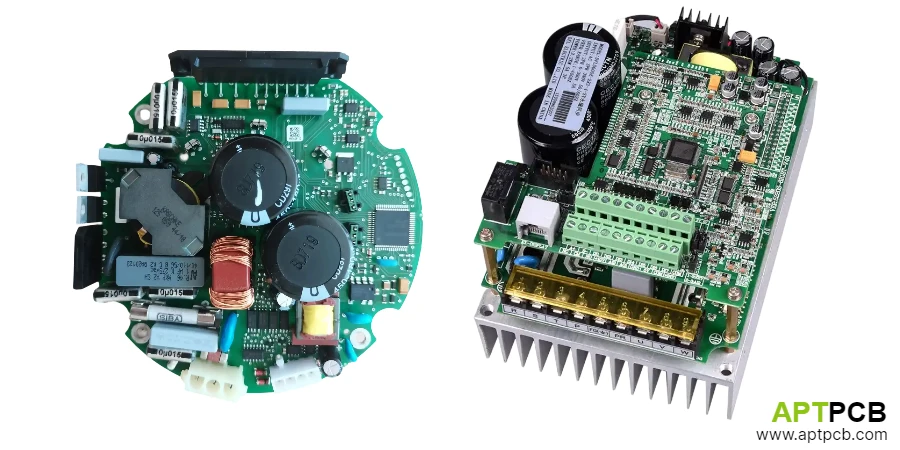
Motor controller power stage topology depends on motor type, voltage range, and performance requirements. Three-phase inverters serve BLDC and AC induction motors; H-bridges or specialized drivers handle stepper motors; single-phase configurations work for simple DC motor control. Each topology presents distinct PCB layout requirements.
Three-phase inverters use six switching devices in a three-leg bridge configuration. The power stage can employ discrete MOSFETs or IGBTs, integrated power modules (IPMs), or intelligent power modules with integrated gate drivers. Module-based approaches simplify layout at higher power levels, while discrete solutions offer flexibility and cost optimization for lower power designs.
For multilayer PCB designs, the power stage layout must minimize DC bus loop inductance—the parasitic inductance in the path from bus capacitor through the switching device pair and back. Each nanohenry of loop inductance creates voltage overshoot during switching that stresses devices and increases EMI.
Topology Design Considerations
- Three-Phase Inverter: Standard for BLDC and AC motor control; six switches with complementary gate drive.
- H-Bridge: Four switches per phase; used for stepper motors or DC brush motors.
- Integrated Modules: IPMs combine multiple switches with gate drivers; simplify layout but limit thermal optimization.
- Bus Bar vs. PCB: High-power designs may use laminated bus bars rather than PCB copper for power distribution.
- Snubber Requirements: Topology-dependent snubber sizing based on device characteristics and layout inductance.
- Brake/Regen: Topology provision for regenerative braking or brake chopper for controlled deceleration.
Gate Driver Integration
Gate drivers translate low-voltage control signals into the drive current needed to switch power semiconductors. Integration level ranges from discrete driver stages to fully integrated smart gate driver ICs with protection and diagnostic features.
High-side gate drivers require either isolated supplies or bootstrap circuits that derive gate drive power from the switched output. Bootstrap designs offer lower cost but impose duty cycle limits—the bootstrap capacitor recharges only when the low-side device conducts. Motor control applications with potential 100% high-side duty (regeneration or DC injection) may require isolated supplies.
The PCB layout for gate drivers must minimize the gate drive loop area while maintaining isolation spacing. The gate drive current path includes the driver output, gate resistor, gate-source terminals, and return path. Inductance in this path causes ringing and affects switching characteristics.
Gate Driver Design
- Bootstrap vs. Isolated: Bootstrap for standard motor control; isolated supplies for applications requiring high-side conduction without periodic low-side switching.
- Gate Resistor Selection: Balances switching speed against ringing and EMI; separate turn-on and turn-off resistors optimize independently.
- Miller Clamp: Active Miller clamp or negative gate bias prevents spurious turn-on from dV/dt coupling.
- DESAT Protection: Desaturation detection for IGBTs provides fast short-circuit protection.
- Propagation Matching: High-side and low-side propagation delay matching prevents shoot-through.
- Dead-Time Generation: Hardware dead-time insertion as backup to software dead-time programming.
Position and Current Sensing
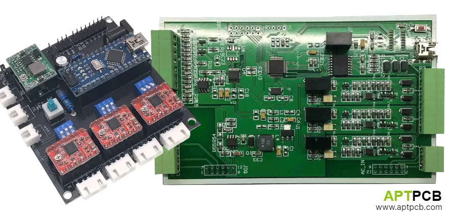
Motor control algorithms require accurate position and current feedback. Position sensing uses Hall sensors for six-step BLDC control, optical or magnetic encoders for field-oriented control, or sensorless techniques that estimate position from back-EMF or current signatures. Current sensing enables torque control and overcurrent protection.
Hall sensor interfaces receive low-voltage digital signals from sensors mounted in the motor. The PCB must condition these signals against noise pickup from motor cables and power switching. Differential transmission or signal conditioning at the motor reduces noise susceptibility for long cable runs.
Current sensing accuracy requirements vary with control approach. Six-step BLDC control tolerates ±5% current sensing accuracy, while high-performance field-oriented control benefits from ±1% accuracy. Shunt-based sensing with isolated amplifiers achieves this accuracy at lower cost than Hall-effect current sensors, with the testing and quality processes ensuring sensing calibration accuracy.
Sensing Implementation
- Hall Sensor Interface: Schmitt trigger inputs with filtering for noise immunity; pull-up resistors sized for cable length.
- Encoder Interface: Differential line receivers for incremental encoders; serial interface for absolute encoders.
- Current Shunt Placement: DC link shunt measures total current; leg shunts enable phase current reconstruction.
- Isolated Amplifiers: Reinforced isolation rating for amplifiers measuring high-side currents.
- Sampling Timing: ADC sampling synchronized with PWM to measure during stable current periods.
- Sensorless Techniques: BEMF zero-crossing detection or high-frequency injection for position estimation.
Digital Control Implementation
Digital motor control executes on microcontrollers or DSPs with specialized peripherals for PWM generation, ADC synchronization, and encoder processing. The PCB must support these functions while minimizing noise coupling from power stages to digital circuits.
PWM generation requires hardware timers with features for complementary outputs, dead-time insertion, and synchronized ADC triggering. Center-aligned PWM reduces current ripple and enables mid-carrier sampling for accurate current measurement. The PWM resolution and carrier frequency selection affects achievable control bandwidth and audible noise.
Control algorithm execution occurs within the PWM cycle period—typically 50-100μs for 10-20kHz PWM. The complete sequence of ADC sampling, control calculation, and PWM update must complete within this window with deterministic timing. Industrial control PCB designs must support real-time performance requirements.
Digital Control Architecture
- Processor Selection: Motor control DSPs or MCUs with integrated PWM, ADC, and encoder peripherals.
- PWM Peripheral: Hardware supports complementary outputs, programmable dead-time, fault inputs, and ADC triggers.
- ADC Performance: 12-bit resolution minimum; 1-2μs conversion time for current loop applications.
- Encoder Hardware: Quadrature decoder counts without software intervention; capture function timestamps index pulses.
- Communication Interface: CAN, Ethernet, or fieldbus for command input and diagnostics.
- Watchdog and Fault: Hardware watchdog and fault inputs that disable PWM independent of software.
Thermal Management Strategies
Motor controllers dissipate power in switching and conduction losses that vary with load and switching frequency. The thermal design must handle both continuous operation at rated load and transient overload conditions during motor starting or acceleration.
Power semiconductor mounting determines thermal resistance from junction to ambient. PCB-mounted devices rely on copper spreading and thermal vias to conduct heat; higher-power designs mount devices to heatsinks or cold plates with thermal interface material. The thermal PCB design must provide adequate thermal paths within layout constraints.
Motor controllers often operate in enclosed spaces—motor housings, equipment cabinets, or vehicle compartments—where ambient temperature may reach 85°C or higher. Component selection and thermal design must account for these elevated ambients while maintaining reliable operation.
Thermal Design Elements
- Thermal Resistance Path: Design junction-to-ambient thermal resistance consistent with power dissipation and temperature limits.
- Copper Weight: 2-4 oz copper in power areas for current carrying and thermal spreading.
- Thermal Via Arrays: Via arrays under power packages reduce thermal resistance to internal layers.
- Heatsink Integration: High-power designs mount semiconductors to external heatsinks through thermal interface material.
- Temperature Sensing: NTC thermistors near power devices enable thermal protection.
- Derating Definition: Clear specification of current capacity versus ambient temperature.
EMC Compliance Approaches
Motor controllers generate EMI from high-frequency switching and radiate through motor cables that act as antennas. Meeting EMC requirements involves filtering, shielding, and layout techniques coordinated across the power stage, control circuits, and system interconnections.
Conducted emissions filtering at the DC input uses common-mode chokes and differential capacitors to attenuate emissions from the PWM switching. Filter design must achieve required attenuation while handling motor current without saturation. The EMC testing processes verify filter effectiveness across the operating range.
Motor cable emissions depend on switching edge rates, cable length, and shielding. Output filters (dV/dt or sine-wave filters) slow output voltage transitions to reduce high-frequency content. These filters also protect motor insulation from voltage spikes that occur with long cable lengths.
EMC Design Approaches
- Input Filtering: Multi-stage common-mode and differential-mode filtering at DC or AC input.
- Output dV/dt Control: dV/dt filters limit output voltage rise rate; reduce motor bearing currents and EMI.
- Cable Shielding: Shielded motor cables with proper termination reduce radiated emissions.
- PWM Frequency Selection: Avoid PWM frequencies that create emissions at sensitive receiver frequencies.
- Spread Spectrum: Spread spectrum PWM reduces peak emissions at PWM frequency and harmonics.
- Ground Plane Integrity: Continuous ground planes minimize loop areas and control return paths.
Summary
Motor controller PCB design balances power handling efficiency, control precision, thermal management, and EMC compliance across applications from compact embedded drives to full-featured industrial controllers. The fundamental principles apply regardless of scale—minimize switching loop inductance, maintain signal integrity for sensing and control, and manage thermal paths for reliable operation. Implementation details vary with power level, motor type, and application requirements, but successful designs share attention to these core engineering concerns.