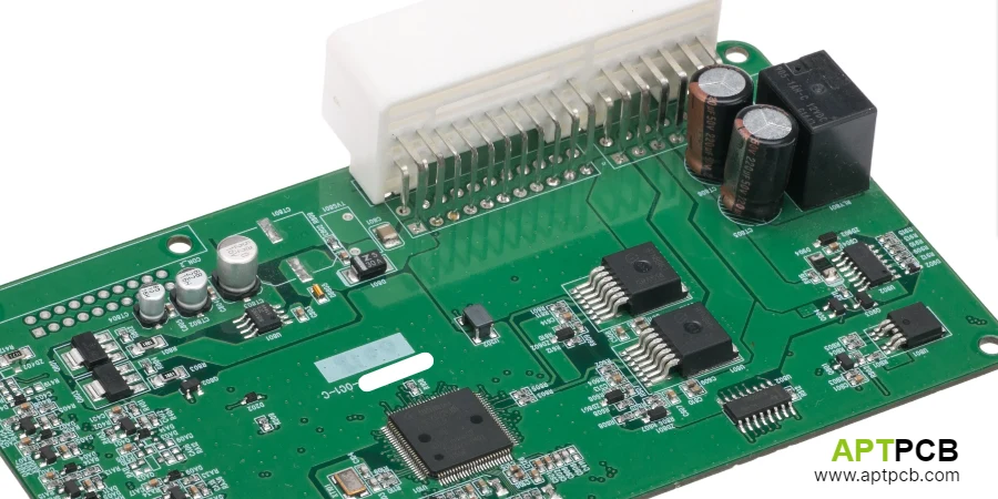
Robotics controllers orchestrate multiple motion axes with millisecond-level synchronization while processing sensor data for environment perception, collision detection, and force control. The PCB must support deterministic real-time processing, high-bandwidth communication between distributed elements, and safety functions that protect humans working alongside robots.
This guide covers PCB engineering decisions critical to robotics controller performance, reliability, and safety compliance.
In This Guide
- Multi-Axis Control Architecture
- Real-Time Communication Networks
- Sensor Integration and Fusion
- Force/Torque Sensing Implementation
- Functional Safety Architecture
- Thermal and Mechanical Design
Multi-Axis Control Architecture
Industrial robots typically coordinate 6-7 axes for manipulator motion plus additional axes for positioners or tracks. Each axis requires position control loops running at 1-4kHz update rates with sub-millisecond synchronization between axes. The controller PCB architecture must support this processing load with deterministic timing.
Centralized architectures place all axis controllers on a single PCB or in a central controller cabinet, with power electronics distributed to motor locations. This approach simplifies synchronization but requires long cable runs for encoder signals and motor power. Decentralized architectures distribute intelligence to individual axis drives, connected via High-Speed PCB routing practices.
The central controller PCB handles trajectory planning, kinematic calculations, and supervision while axis-level loops handle current control and commutation. This hierarchy allows the central controller to use microsecond-level position commands that axis drives interpolate and execute with their own encoder feedback.
Multi-Axis Architecture Elements
- Processing Platform: Multi-core processors or FPGA+DSP combinations for parallel axis computation.
- Synchronization: Hardware sync signals distribute common timing reference to all axis controllers.
- Trajectory Interpolation: Position interpolation between trajectory points at 1-4ms intervals.
- Kinematic Calculation: Forward and inverse kinematics execute in real-time for coordinated motion.
- Axis Communication: High-speed fieldbus (EtherCAT, SERCOS) connects central controller to distributed drives.
- Buffer Management: Motion queue buffers absorb communication latency variations.
Real-Time Communication Networks
Robotics controllers use real-time Ethernet protocols that guarantee message delivery within microsecond-level timing windows. EtherCAT, PROFINET IRT, and SERCOS III provide deterministic communication that maintains axis synchronization across distributed systems.
EtherCAT achieves sub-microsecond synchronization through distributed clock (DC) mechanism where slave devices synchronize their local oscillators to a reference clock propagated through the network. PCB design for EtherCAT controllers must support the PHY requirements and DC synchronization hardware.
The network also carries I/O data for sensors, safety signals, and auxiliary equipment. An HDI PCB layout must maintain signal integrity across connectors and through the PHY interface while meeting industrial EMC requirements.
Real-Time Network Implementation
- EtherCAT ESC: EtherCAT Slave Controller IC with integrated DC support for axis drives.
- PHY Selection: Industrial-rated Ethernet PHY with 100Mbps operation and extended temperature range.
- Clock Quality: Local oscillator with low jitter for distributed clock synchronization accuracy.
- Transformer Isolation: 1500Vrms isolation via magnetics per industrial Ethernet requirements.
- Redundancy Options: Cable redundancy for critical applications; automatic failover on cable break.
- Topology Flexibility: Support for daisy-chain, star, and mixed topologies in the network.
Sensor Integration and Fusion
Modern robots integrate multiple sensor types—vision systems, proximity sensors, force/torque sensors, and safety devices—that must synchronize with motion control for responsive behavior. The controller PCB aggregates these inputs with timing correlation that enables reactive motion.
Vision processing for robotic guidance typically occurs in dedicated processors or accelerators due to computational demands. The controller interfaces to vision systems via GigE Vision or Camera Link, receiving processed position data rather than raw images. Time-stamping ensures vision data aligns correctly with robot position despite processing latency.
Proximity and safety sensors require faster response—typically under 10ms from obstacle detection to motion stop. These sensors connect directly to the controller or through the real-time network with appropriate priority handling. A careful high-speed PCB design approach must maintain signal integrity for reliable detection.
Sensor Integration Design
- Vision Interface: GigE Vision or USB3 Vision for camera connectivity; FPGA-based accelerators for real-time processing.
- Time Synchronization: IEEE 1588 PTP synchronizes vision timestamps with motion control timing.
- Analog Sensor Inputs: High-resolution ADCs for analog sensors; differential inputs for noise immunity.
- Digital I/O: Optocoupler-isolated digital inputs for safety sensors and discrete signals.
- Sensor Fusion Processing: FPGA or dedicated processors handle sensor data fusion calculations.
- Latency Management: End-to-end latency budgeted from sensor event to motion response.
Force/Torque Sensing Implementation
Force/torque sensors enable compliant motion, assembly operations, and human-robot interaction safety. The controller must process multi-axis force data with bandwidth sufficient for stable force control loops—typically 500Hz-1kHz update rates.
Force/torque sensors typically use strain gauge bridges that produce millivolt-level signals requiring precision amplification and analog-to-digital conversion. The PCB analog front-end must achieve 16-bit resolution with low noise floor while rejecting EMI from motor drives and power electronics in the robot system.
Force control loops close around sensed force rather than position, enabling applications like grinding, polishing, or assembly where maintaining force is more important than precise position. The Rigid-Flex PCB for force sensing must achieve the dynamic range and bandwidth these applications require.
Force Sensing Design
- Signal Conditioning: Precision instrumentation amplifiers for strain gauge bridge signals.
- ADC Requirements: 16-bit minimum resolution; simultaneous sampling for 6-axis force/torque.
- Noise Rejection: Differential inputs, filtering, and shielding for µV-level signal measurement.
- Calibration: Factory calibration with coefficients stored in sensor or controller; field calibration provision.
- Safety Integration: Force limiting integrates with safety system for collaborative robot applications.
- Update Rate: 500Hz-1kHz force data update rate for stable force control loops.
Functional Safety Architecture
Collaborative robots require safety functions certified to PLd/Cat.3 or SIL2 per ISO 13849 and IEC 62443. The controller PCB implements safety functions including safe limited speed (SLS), safe limited force (SLF), and safe standstill monitoring through architectures that achieve required diagnostic coverage and failure tolerance.
Safety architecture typically employs dual-channel processing where two independent processors monitor safety-relevant parameters and compare results. Disagreement triggers safe stop. The PCB must maintain independence between channels—separate supplies, separate sensing, and physical separation—to prevent common-cause failures.
Industrial safety PCB design for robotics controllers requires detailed failure mode analysis and documentation. Safety certification evidence includes schematic review, PCB layout analysis, and testing evidence demonstrating safety function performance under fault conditions.
Safety Architecture Elements
- Dual-Channel Processing: Independent processors executing safety monitoring with result comparison.
- Channel Independence: Separate power supplies, ADCs, and sensing for each safety channel.
- Safe Encoder: Redundant or safety-rated absolute encoders for position monitoring.
- Force/Torque Safety: Redundant force sensing or safety-rated sensors for force limiting functions.
- Response Time: End-to-end safety function response time budgeted and verified.
- Diagnostic Coverage: Hardware diagnostics achieve required diagnostic coverage (DC) per safety level.
Thermal and Mechanical Design
Robotics controllers operate in environments from climate-controlled cells to harsh factory floors, often mounted directly on robot structures where vibration and temperature fluctuations challenge reliability. The PCB must survive these conditions while maintaining control performance.
Vibration resistance requires attention to component mounting and PCB fixation. Heavy components—transformers, large capacitors, connectors—experience significant mechanical stress under vibration and may require staking or mechanical reinforcement. The PCB manufacturing quality process must ensure solder joint integrity under vibration stress.
Thermal design must accommodate both continuous dissipation from processing electronics and variable dissipation from communication interfaces and I/O. Controllers mounted on robot arms face additional constraints from available mounting volume and heat rejection paths.
Mechanical and Thermal Design
- Vibration Qualification: Design and testing for vibration levels per robot specification (often >2g).
- Shock Resistance: Withstand handling and emergency stop events without damage.
- Temperature Range: -10°C to +50°C ambient typical; some applications require extended range.
- Conformal Coating: Selective coating protects against contamination while allowing thermal dissipation.
- Connector Reliability: Industrial-rated connectors with positive locking for vibration resistance.
- Thermal Paths: Component placement and copper areas optimized for heat transfer to available cooling.
Summary
Robotics controller PCB design integrates real-time motion control, sensor fusion, safety functions, and industrial communication in systems that must perform reliably in challenging environments. The combination of precision analog sensing, high-speed digital processing, and deterministic communication creates design constraints that require coordinated engineering across multiple domains. Success depends on understanding how these interacting subsystems affect overall system performance and safety.
If you’re planning a robotics controller build, start with our core PCB options here: PCB Manufacturing.