Smart speakers combine challenging audio requirements—far-field voice capture, multi-channel playback, and acoustic echo cancellation—with computing capabilities for voice processing and smart home connectivity. The PCB design must balance analog audio performance with digital noise management, thermal considerations for amplifier power dissipation, and antenna integration for reliable WiFi and Bluetooth connectivity.
This guide examines the PCB-specific challenges in smart speaker design: microphone array implementation for voice capture quality, audio amplification and speaker driver design, voice processing DSP requirements, thermal management for Class-D amplifiers, and wireless connectivity integration within audio-sensitive systems.
In This Guide
- Microphone Array Design for Far-Field Voice Capture
- Audio DSP and Voice Processing Implementation
- Class-D Amplifier Layout and Thermal Management
- Wireless Connectivity in Audio-Sensitive Systems
- Power Supply Design for Audio Quality
- Manufacturing Considerations for Audio Products
Microphone Array Design for Far-Field Voice Capture
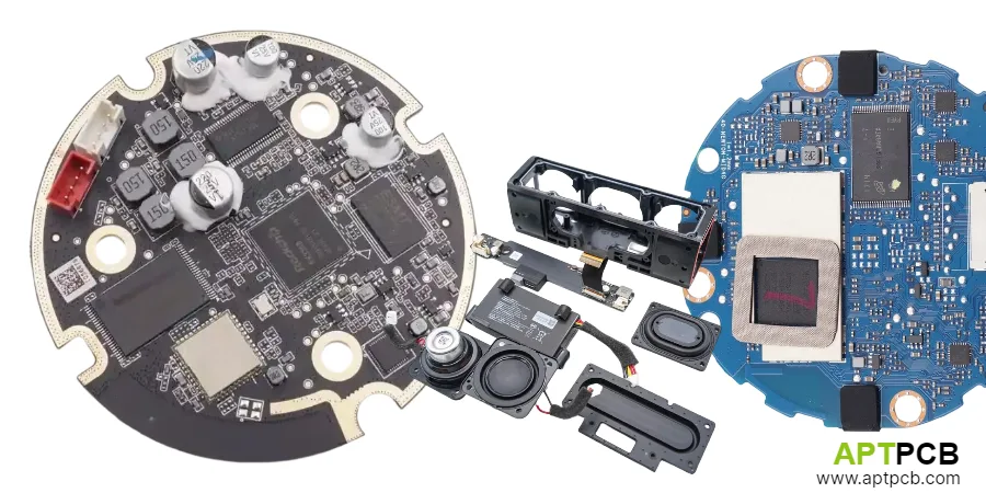
Far-field voice capture—reliably capturing voice commands from several meters away in typical room acoustics—requires multiple microphones configured as arrays for spatial filtering and noise rejection. Smart speakers typically use 2-8 MEMS microphones arranged in circular or linear patterns, with geometry optimized for beamforming algorithms that isolate voice from background noise.
PCB implementation of microphone arrays demands careful attention to acoustic coupling, electrical noise immunity, and precise microphone positioning. Each microphone element requires consistent acoustic path to sound source (port design) and isolated analog domain that prevents digital noise from corrupting the sensitive microphone signal.
Microphone Array Implementation
- Microphone Type: Digital MEMS microphones (PDM or I2S output) simplify routing and provide immunity to analog noise coupling; SNR specifications of 65dB or higher necessary for voice quality.
- Array Geometry: Microphone spacing determines beamforming capability; typical smart speaker arrays use 35-50mm spacing for optimal performance at voice frequencies (300Hz-3kHz).
- Acoustic Port Design: Microphone port holes through PCB require precise size (typically 0.5-1.0mm) and position alignment with microphone element; sealed acoustic path prevents ambient noise entry.
- Digital Routing: PDM clock lines require controlled impedance and matched lengths to microphones; timing skew between microphones degrades beamforming performance.
- Ground Isolation: Dedicated microphone ground pour connected to system ground at single point; prevents current return from other circuits coupling into sensitive microphone signals.
- Component Placement: Keep microphones away from noise sources (switching regulators, motors, WiFi modules); minimum 15mm clearance to noisy components.
Microphone array performance depends on both electrical implementation and acoustic design—enclosure geometry significantly affects voice capture quality beyond PCB considerations.
Audio DSP and Voice Processing Implementation
Smart speakers require substantial signal processing capability for acoustic echo cancellation (AEC), noise reduction, beamforming, and wake word detection—all running simultaneously during voice interaction. Dedicated DSP processors or application processor cores handle these algorithms, requiring memory bandwidth for audio buffering and low-latency I/O paths to microphone arrays and audio output.
The DSP implementation must maintain low latency through the audio pipeline—excessive processing delay degrades echo cancellation performance and creates perceivable lag in voice interaction. PCB design affects latency through memory interface performance and I/O path efficiency.
DSP Implementation Considerations
- Processor Selection: Dedicated audio DSPs (Qualcomm, Synaptics) offer optimized voice processing; application processors with DSP cores provide flexibility but may increase system complexity.
- Memory Interface: Voice processing buffers require memory bandwidth; DDR interface routing follows standard high-speed guidelines with length matching and impedance control.
- I2S Routing: Audio data from microphone codec to DSP, and from DSP to amplifier, uses I2S serial interface; route as differential pairs with ground reference for noise immunity.
- Clock Distribution: Audio clocks (MCLK, BCLK, LRCLK) require clean routing with minimal jitter; PLL-based clock generation should use filtered power supplies.
- Decoupling Strategy: DSP power rails require local decoupling for clean operation; separate analog and digital supplies if DSP has split power domains.
- Debug Access: Audio processing debug often requires I2S monitoring or DSP debug interface access; design test points or headers for development support.
Voice processing quality depends on algorithm implementation but PCB design affects the noise floor and timing accuracy that algorithms require for optimal performance.
Class-D Amplifier Layout and Thermal Management
Smart speaker audio output typically uses Class-D amplification for efficiency—particularly important given compact enclosure sizes and desire for fanless operation. Class-D amplifiers dissipate less power than linear amplifiers but still generate heat that must be managed (typical efficiency 85-90% means 10-15% of output power becomes heat; a 20W speaker still dissipates 2-3W thermally).
Class-D amplifiers generate high-frequency switching noise (typically 300kHz-1MHz carrier frequency) that can radiate into sensitive circuits if layout practices are poor. The combination of switching noise management and thermal design makes amplifier section layout critical for overall product quality.
Class-D Layout Best Practices
- Power Stage Placement: Place power stage MOSFETs and output inductor close together with short, wide traces; minimize loop area for switching current path.
- Output Inductor Selection: Shielded inductors prevent radiation of switching frequency; unshielded inductors require careful placement away from microphones and WiFi antenna.
- Thermal Relief: Amplifier IC thermal pad requires adequate copper area and thermal vias for heat dissipation; 2-3× pad area copper pour on inner layers for heat spreading.
- Ground Return Path: Speaker return current should flow through dedicated path separate from sensitive analog ground; use thick traces or copper pour for low-impedance return.
- Output Filter Design: LC output filter components place close to amplifier output; minimizes trace inductance that can cause EMI radiation.
- EMI Containment: Shield can over amplifier section may be necessary for regulatory compliance; design shield ground connections and component clearances.
Amplifier thermal performance in sealed enclosures often limits maximum sustained power output—thermal simulation validates that design achieves required continuous power specifications.
Wireless Connectivity in Audio-Sensitive Systems
Smart speakers require WiFi for cloud connectivity and typically Bluetooth for local streaming and device pairing. These wireless systems operate at frequencies (2.4GHz and 5GHz) that can interfere with audio circuits through direct coupling and demodulation of RF signals by non-linear elements in audio paths.
The challenge intensifies because microphones must remain accessible (not shielded) for acoustic input while nearby wireless transmitters operate at power levels that create significant near-field strength. Careful frequency planning, shielding, and PCB layout isolate RF energy from audio circuits.
RF-Audio Coexistence
- Spatial Separation: Position WiFi module and antenna as far as practical from microphone array; typical smart speaker geometry places antenna near enclosure top, microphones on sides.
- Ground Plane Strategy: Solid ground plane beneath both WiFi section and audio section, but consider whether same plane or isolated planes with controlled connection better serves your design.
- Filter on Supplies: Ferrite beads on power supplies to microphone amplifiers attenuate high-frequency noise conducted from digital circuits.
- RF Shield Cans: Metal shields over WiFi module contain radiation; shields over audio preamp stages prevent pickup—use shields strategically rather than everywhere.
- Antenna Isolation: Antenna ground clearance regions should not extend into sensitive analog areas; plan keepout regions during early layout.
- Coexistence Testing: Test voice capture quality during active WiFi transmission; issues may not appear at low signal strength but emerge during high-power transmission.
Wireless integration in audio products requires iterative verification during development—simulation cannot fully predict RF-to-audio coupling in complex geometries.
Power Supply Design for Audio Quality
Audio performance depends heavily on power supply quality—noise, ripple, and load regulation all affect signal-to-noise ratio and audio fidelity. Smart speakers present particular challenges because the same supply system must power noisy digital processors, switching amplifiers, and sensitive analog circuits.
Effective power supply architecture isolates noise-generating stages from sensitive circuits through separate regulation stages, filtering, and careful ground management. The goal is preventing supply-coupled noise from degrading microphone sensitivity or introducing audible artifacts in audio output.
Power Supply Architecture
- Supply Separation: Analog microphone supplies should have separate LDO regulation from digital processor supplies; amplifier may use switched supply with adequate filtering.
- LDO Selection: Low-noise LDOs (<10μVRMS) for microphone bias and analog preamp supplies; PSRR specification matters—select regulators with high PSRR at audio frequencies.
- Input Filtering: Ferrite beads and LC filters between noisy supplies and sensitive stages; filter design should attenuate switching frequencies while maintaining transient response.
- Ground Topology: Star ground or carefully-planned ground connections prevent return currents from noisy stages coupling into sensitive circuits; single-point connections between ground regions.
- Bypass Strategy: Local decoupling at each IC; bulk capacitance at supply entry points; ESR considerations for audio-frequency filtering effectiveness.
- Layout Discipline: Power traces should not cross or run parallel to sensitive audio signals; separate power routing regions from signal routing regions where possible.
Power supply design directly affects achievable signal-to-noise performance—noise floor limitations often trace to power supply implementation rather than component selection.
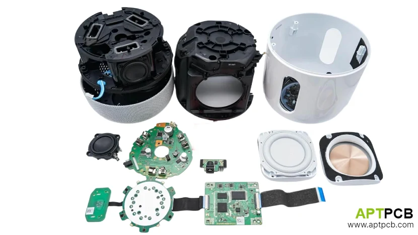
Manufacturing Considerations for Audio Products
Audio product manufacturing adds considerations beyond standard PCB assembly—acoustic components require precise positioning, audio performance verification requires specialized test equipment, and cosmetic quality matters for consumer-facing products. Production planning must address these requirements while maintaining cost efficiency.
The microphone array implementation particularly affects manufacturing—acoustic port alignment between PCB and enclosure, microphone matching within arrays, and seal integrity around acoustic paths all require verification that typical electronics testing does not address.
Manufacturing Requirements
- Microphone Handling: MEMS microphones are sensitive to moisture and ESD; proper handling procedures prevent damage—verify supplier specifications for MSL rating and reflow parameters.
- Acoustic Path Verification: Test acoustic coupling between microphone elements and external environment; seal defects cause inconsistent voice capture performance.
- Audio Test Integration: Production testing should include audio frequency response measurement, microphone sensitivity matching, and speaker output verification.
- Thermal Verification: Amplifier thermal performance verification during production; spot-check temperature rise under load confirms thermal design adequacy.
- Wireless Calibration: WiFi and Bluetooth often require RF calibration during production; test fixture and calibration procedure integration necessary.
- Cosmetic Standards: Consumer audio products face cosmetic requirements on visible PCB areas; specify acceptability criteria for solder appearance, marking clarity, and component alignment.
Production of audio consumer electronics benefits from comprehensive assembly services that integrate PCB fabrication, component assembly, and functional testing.
Technical Summary
Smart speaker PCB design combines audio engineering fundamentals with modern digital system integration challenges. The microphone array implementation, voice processing DSP, Class-D amplification, and wireless connectivity each present distinct requirements that must be addressed without mutual interference.
Critical success factors include microphone array layout for consistent voice capture, amplifier thermal management within compact enclosures, RF isolation to prevent wireless interference with audio paths, and power supply architecture that provides clean power to sensitive analog stages.
Manufacturing partnerships for smart speakers should evaluate audio-specific capabilities—microphone handling, acoustic testing, and audio performance verification—beyond standard SMT assembly competencies. Early production planning ensures test coverage addresses audio-specific quality metrics.