
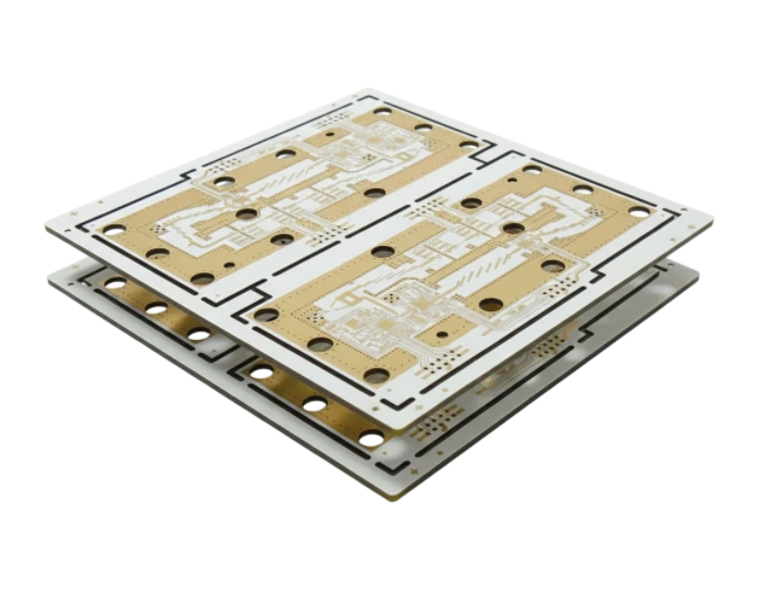
In high-speed and radio-frequency (RF) electronics, the substrate supporting your copper traces is never just an inert mechanical holder. It is an active electromagnetic medium. The single most critical parameter governing how electrical signals travel through that medium is the dielectric constant, often abbreviated as Dk or denoted by the Greek symbol $\varepsilon_r$ (relative permittivity).
Whether you are matching a 50 Ω transmission line for a 5G transceiver, calculating phase delay across differential pairs, or budgeting power loss in automotive radar, understanding the physical definition, mathematical formula, and manufacturing tolerances of the dielectric constant determines whether your circuit functions cleanly or fails regulatory compliance.
This engineering guide explains what dielectric constant means, how to calculate it, how common substrates compare, and when performance demands upgrading from standard FR-4 to specialized RF laminates.
Key takeaways
- Dielectric constant meaning: The dielectric constant represents the ratio of electric field energy stored in a material compared to vacuum when an electric potential is applied.
- Units and symbol: Because it is a relative ratio of permittivities ($\varepsilon / \varepsilon_0$), the dielectric constant is dimensionless (it has no physical units) and is symbolized as $\varepsilon_r$ or Dk.
- Signal propagation speed: Propagation velocity is inversely proportional to the square root of the effective dielectric constant: $v_p = c / \sqrt{\varepsilon_{\text{eff}}}$. A higher Dk slows down signals.
- Impedance control: For a fixed copper thickness and dielectric height, a higher Dk requires narrower traces to maintain a target 50 Ω characteristic impedance.
- Frequency dependency: Dk drops as signal frequency increases. Premium RF laminates maintain a nearly flat Dk curve across GHz spectrums, while standard FR-4 exhibits noticeable dispersion.
What is dielectric constant? Definition and symbol
To understand what dielectric constant is in engineering practice, we examine how insulating materials respond to electric fields. When an alternating electric field passes through an insulating dielectric material, the molecules polarize—their positive and negative charges shift slightly against the applied voltage. This polarization stores electrostatic energy.
The dielectric constant (also widely termed relative permittivity) quantifies an insulating material's ability to store electrostatic energy relative to empty space. The symbol for dielectric constant in physics literature is $\kappa$ (kappa) or $\varepsilon_r$, while IPC standards and laminate manufacturers universally denote it as Dk.
A vacuum has a dielectric constant of exactly 1.0. Dry air is approximately 1.0006, meaning air behaves almost identically to a vacuum for electromagnetic wave propagation. By contrast, PCB substrate materials exhibit Dk values ranging from roughly 2.1 (pure PTFE) to 9.8 (alumina ceramic, $\text{Al}_2\text{O}_3$), and between 3.8 and 4.6 for standard glass-reinforced epoxy (FR-4).
Formula, units, and permittivity explained
Mathematically, the formula for dielectric constant compares the absolute permittivity of the material to the permittivity of free space:
$$\varepsilon_r = \frac{\varepsilon}{\varepsilon_0}$$
Where:
- $\varepsilon_r$ (or Dk) is the relative dielectric constant (dimensionless).
- $\varepsilon$ is the absolute permittivity of the dielectric medium, measured in Farads per meter ($\text{F/m}$).
- $\varepsilon_0$ is the vacuum permittivity constant, equal to approximately $8.854 \times 10^{-12} \text{ F/m}$.
Dielectric constant units
Because both numerator ($\varepsilon$) and denominator ($\varepsilon_0$) share the unit of Farads per meter ($\text{F/m}$), the units cancel out completely. Therefore, dielectric constant has no units—it is a pure scalar ratio. If someone asks for "units for dielectric constant" or "dielectric constant unit," the technically precise answer is dimensionless (unitless).
Capacitor formula representation
In circuit terms, dielectric constant can also be expressed through parallel-plate capacitance:
$$C = \frac{\varepsilon_r \varepsilon_0 A}{d}$$
Where $A$ is the plate area and $d$ is the dielectric separation distance. If you replace air with an FR-4 laminate ($Dk \approx 4.4$) while holding geometry identical, the mutual capacitance increases by a factor of 4.4. In high-density printed circuits, this directly inflates parasitic capacitance between adjacent traces and ground planes.
Dielectric constant of air and common PCB materials
Different resin systems, glass weaves, and ceramic fillers yield radically different dielectric properties. The table below compares common PCB base materials measured at standard test frequencies:
| Material Type | Common Trade Names / Spec | Typical Dk (1 GHz) | Typical Dk (10 GHz) | Loss Tangent (Df @ 10 GHz) | Primary Application |
|---|---|---|---|---|---|
| Vacuum | Ideal reference | 1.0000 | 1.0000 | 0.0000 | Theoretical baseline |
| Air | Dry ambient air | 1.0006 | 1.0006 | ~0.0000 | Stripline air gaps, coax air lines |
| PTFE (Teflon) | Unreinforced fluoropolymer | 2.10 | 2.10 | 0.0004 | Microwave radar, mil-aero |
| Woven Glass PTFE | Rogers RT/duroid 5880 | 2.20 | 2.20 | 0.0009 | Ku/Ka-band satellite comms |
| Hydrocarbon Ceramic | Rogers RO4350B | 3.66 | 3.48 | 0.0037 | Cellular base stations, 24 GHz radar |
| High-Speed Epoxy | Panasonic Megtron 6 | 3.71 | 3.65 | 0.0040 | 112G PAM4 backplanes, PCIe 5.0/6.0 |
| Low-Loss FR-4 | Isola FR408HR | 3.68 | 3.63 | 0.0092 | High-speed digital servers |
| Standard Mid-Tg FR-4 | Kingboard KB-6160 | 4.40 | 4.15 | 0.0200 | Consumer electronics, industrial controls |
| Alumina Ceramic | $\text{Al}_2\text{O}_3$ Ceramic substrate | 9.80 | 9.60 | 0.0008 | Power modules, hermetic hybrids |
Notice that the $\text{Al}_2\text{O}_3$ dielectric constant (9.8) is among the highest utilized in electronic packaging, providing intense capacitive charge storage in compact planar geometries, whereas fluoropolymers sit near the bottom (2.1 to 2.2).
Why Dk matters in PCB design
The dielectric constant governs three foundational pillars of printed circuit performance:
1. Signal propagation speed ($v_p$) and phase delay
Electromagnetic waves travel at the speed of light in vacuum ($c \approx 3 \times 10^8 \text{ m/s}$, or roughly 11.8 inches per nanosecond). Inside a PCB dielectric, the electromagnetic wave slows down according to:
$$v_p = \frac{c}{\sqrt{\varepsilon_{\text{eff}}}}$$
Where $\varepsilon_{\text{eff}}$ is the effective dielectric constant (a weighted average between the laminate and surrounding air/soldermask for surface microstrips).
- In air ($\text{Dk} = 1$): $v_p \approx 11.8 \text{ in/ns}$ (propagation delay $t_{pd} \approx 85 \text{ ps/in}$).
- In standard FR-4 ($\text{Dk} \approx 4.0$): $v_p \approx 5.9 \text{ in/ns}$ (propagation delay $t_{pd} \approx 170 \text{ ps/in}$).
A higher dielectric constant doubles trace latency. For length-matched differential pairs in DDR5 or PCIe buses, variations in local Dk due to glass bundle alignment cause timing skew and jitter.
2. Characteristic trace impedance ($Z_0$)
The characteristic impedance of a transmission line depends inversely on the square root of Dk:
$$Z_0 \propto \frac{1}{\sqrt{\varepsilon_{\text{eff}}}}$$
When the dielectric constant increases, you must either widen trace separation from reference planes or narrow the trace width to maintain a target 50 Ω single-ended or 100 Ω differential impedance. A higher Dk forces extremely narrow traces on thin cores, increasing resistive copper loss ($I^2R$).
3. Cross-talk and capacitive parasitic coupling
A higher substrate Dk increases mutual capacitance between neighboring parallel conductors, exacerbating near-end (NEXT) and far-end (FEXT) crosstalk unless routing pitch is increased.
Dk vs frequency and dissipation factor (Df)
Two common pitfalls trap PCB designers: treating Dk as a fixed constant and ignoring dissipation factor (Df).
Dielectric dispersion across frequency
The dielectric constant is not truly constant. As signal frequency escalates from 100 MHz to 10 GHz and beyond, polar molecules inside the resin matrix can no longer rotate fast enough to keep up with the alternating field oscillations. Consequently, Dk decreases with frequency—a phenomenon known as dielectric dispersion.
In standard FR-4, Dk may measure 4.5 at 1 MHz, 4.3 at 1 GHz, and fall to 4.1 at 10 GHz. This frequency-dependent change alters phase velocity across broad frequency harmonics, causing pulse degradation and eye-diagram closure in multi-gigabit digital channels.
Df (Loss Tangent) relationship
While Dk determines trace velocity and capacitance, the dissipation factor (Df) determines how much electromagnetic energy is converted into waste heat as waves travel down the trace. Dielectric attenuation ($\alpha_d$) in decibels per inch is given by:
$$\alpha_d \approx 2.32 \cdot f \cdot \tan(\delta) \cdot \sqrt{\varepsilon_{\text{eff}}} \quad [\text{dB/in}]$$
Where $f$ is frequency in GHz and $\tan(\delta)$ is Df. At frequencies exceeding 5 GHz, dielectric loss dominates over conductor skin-effect loss.
When to leave FR-4 for high-frequency materials
FR-4 is the cost-effective workhorse of the electronics industry, but physical laws impose clear operational limits. Engineers must transition to high-speed digital (HSD) or RF-grade laminates when designs encounter:
- Digital baud rates over 10 Gbps: Channels operating PCIe 4.0/5.0, 25G Ethernet, or SAS-4 experience unacceptable channel insertion loss on standard FR-4.
- Analog RF frequencies exceeding 3 GHz: For 5.8 GHz Wi-Fi 6E/7, 24 GHz ISM, or 77 GHz radar, dielectric attenuation on standard FR-4 is prohibitive.
- Phase-critical phased array antennas: Automotive radar and beamforming arrays demand tight Dk tolerances (e.g., Rogers RO4835 with Dk specified at $3.48 \pm 0.05$), whereas standard FR-4 can vary by $\pm 0.3$ across lots.
- Thermal stability requirements: High-power RF amplifiers cause substrate heating. Standard FR-4 exhibits high thermal coefficient of dielectric constant ($TcDk \approx +200 \text{ to } +300 \text{ ppm/}^\circ\text{C}$), whereas ceramic-filled laminates offer near-zero $TcDk$.
When migrating to advanced substrates, partnering with an experienced manufacturer for high frequency PCB fabrication ensures proper plasma desmear, specialized etching chemistry, and controlled-impedance coupon testing.
How to specify Dk on a fabrication drawing
When submitting manufacturing files for controlled-impedance boards:
- Specify target impedance over absolute Dk: Board fabricators maintain active coupon databases that compensate for resin content, pressed prepreg thickness, and copper foil surface roughness. Call out
$50\,\Omega \pm 10\%$ single-ended on Layer 1rather than demanding a rigid theoretical Dk number. - Reference manufacturer slash sheets: Use IPC-4101 slash sheet standards (e.g., IPC-4101/126 for high-Tg lead-free FR-4, or IPC-4103 for high-frequency hydrocarbon/PTFE substrates).
- Request IPC-2141 / Polar Si9000 modeling: Work directly with the fab house engineering team to run pre-layout stackup calculations before routing.
Frequently Asked Questions
Q: What is the dielectric constant of air compared to vacuum? A: A vacuum is the theoretical baseline with an exact dielectric constant of 1.0000. Dry air at standard atmospheric pressure has a dielectric constant of approximately 1.0006. In practical engineering calculations, air is treated as having a Dk of 1.0.
Q: Does dielectric constant have units? A: No. Dielectric constant represents relative permittivity ($\varepsilon_r = \varepsilon / \varepsilon_0$), which is the ratio of two values measured in Farads per meter ($\text{F/m}$). Because units cancel out, dielectric constant is completely dimensionless.
Q: Why does FR-4 dielectric constant vary between 3.8 and 4.6? A: FR-4 is a composite material made of woven fiberglass cloth ($\text{Dk} \approx 6.0$) and cured epoxy resin ($\text{Dk} \approx 3.2$). The overall Dk depends on the glass-to-resin ratio (glass style like 1080, 2116, or 7628), temperature, and the operating signal frequency.
Q: What is the dielectric constant of Al2O3 (alumina ceramic)? A: Alumina ceramic ($\text{Al}_2\text{O}_3$) exhibits a dielectric constant of approximately 9.6 to 9.8 at 1 GHz. Its high Dk and high thermal conductivity ($24\text{–}30 \text{ W/m}\cdot\text{K}$) make it ideal for compact RF power hybrids and LED packaging.
Q: How does Dk affect signal speed on a PCB? A: Signal velocity on a transmission line is inversely proportional to the square root of the effective dielectric constant ($v_p = c / \sqrt{\varepsilon_{\text{eff}}}$). Higher Dk slows propagation speed and increases latency across trace lengths.